
Foreword
Like other wBW reviews started late last year, the (somewhat) early onset of the white stuff is dictating changes regarding submission and publication. The inView by Third Eye Design product review is one of these protracted activities.
This initial submission provides a wBW First Look view into this new and innovative technology-based motorcycle safety focused product, along with some early functional observations.
*Note: An encompassing in-depth on the road follow-up of the Third Eye Design inView product is planned for the end of winter or early spring – stay tuned for the ride.
Introduction
A prominent focus of wBW remains motorcycle safety; a focus reflected in almost everything undertaken and published over the years.
wBW reviewed what was the first, or one of the first, wireless helmet-based LED brake light products in October 2017 when Rick published the RiderLight Helmet Wireless LED Brake Light article. I never did manage to get my hands on it, but it wasn’t for a lack of trying…
But time and technology do not stand still and many earlier deceleration-based products have come and gone. But, there is a growing array of advanced rear-facing auxiliary lighting products on the market including those from Skene and Admore Lighting that function as stand-alone systems, as opposed to CANbus, interfaced systems like the Clearwater CANopener or HEX ezCAN.
A good example of a multi-function multi-output stand-alone system is the Admore Lighting Smart Brake or ADMSB light bar featuring an onboard microprocessor, accelerometer and high output LEDs for tail, brake, signal, and deceleration-based or dynamic braking output.
Third Eye Design isn’t alone in pursuing products similar in function to the inView, one only needs to look at some of the motorcycle helmets and motorcycle helmet related products on display at CES 2020 including the Tali Connected and Skully Technologies initiatives.
Our own Wade Thiel published a Smart Helmet primer in September 2019 with a great overview and specific insights from current and emerging players like Forcite, Jarvish, and Skully, along with current mainstream helmet manufacturers like Shoei with its prototype IT-HT is shown at CES 2019 and apparently available in Spring 2020. But not yet confirmed though…
As a life-long motorcyclist, a BIG safety advocate and admitted technophile, being able to follow the development of and then review products like the Third Eye Design inView Wireless Helmet Brake and Turn Signal Light System with its universal installation and use approach is all good.
Shopping Now? We Recommend:
webBikeWorld works closely with Amazon to provide our testers with quality products to review. While we have an affiliate relationship and receive a commission from items purchased, this addition comes at no additional cost to you. It is the primary way we pay for our site and reviewers.
Amazon
![]()
Third Eye Design
Third Eye Design was founded on the belief that “(we) can use technology to make the world a better, safer place… and (we) are starting one motorcycle at a time”. Their mission statement, “making motorcyclists safer and more confident, improving visibility and the ride, saving lives” sums it up nicely.

The company designs and manufactures cutting edge technology products focused on a patented ground-breaking design. Headquartered in Pittsford NY with offices in Washington DC and Sorrento FL, the first product is the inView wireless brake and turn signal system, designed and manufactured in the US.
Third Eye Design proudly supports their community through a partnership with ARCWorks, a contract manufacturer staffed by individuals with physical and/or intellectual challenges; they provide packaging and fulfillment services for Third Eye Design.
Introducing the inView
The inView Wireless Helmet Brake and Turn Signal System by Third Eye Design is a technology-based safety product providing increased visibility and awareness of both the motorcycle and rider; a take on things that aren’t always appreciated, nor addressed from active lighting profile perspectives.
Utilizing ultra-low frequency technology for an unprecedented and exclusive design solution with other proprietary (patented) technologies, the inView system uses almost all the helmet module battery power for LED output instead of wireless transceiver-based communications with the vehicle-mounted component.
Three components – vehicle-mounted control module, a wired vehicle-mounted auxiliary LED brake light and the portable helmet module with Red brake LEDs and perimeter-mounted Amber turn signal LEDs form the system.
Key inView Features
- Brake (onboard and deceleration-based braking), turn and four-way hazard output
- Set-n-Forget operation – On and Off with motorcycle ignition, no manual switching needed, helmet module is ‘always on’, wakes up when system is turned on, sleeps when it’s not
- Integration with motorcycle braking and directional systems for concurrent output
- Provides deceleration-based dynamic braking (passive braking) output
- Standalone systems – no CANbus compatible issues
- Ultra-bright LEDs used for Helmet Module and Accessory Brake Module outputs
- Automatic diagnostics test system function including LED module outputs and battery life
- Inversion protection – helmet module mounted upside down? It will let you know
- Helmet Module easily transferred between helmets
- Long battery life/optimal performance using two Lithium-ion AAA batteries, easily replaced
- DIY installation – everything needed is included, less downloadable instructions
- iOS or Android companion App
inView System Components

As identified above, the inView system has three components.
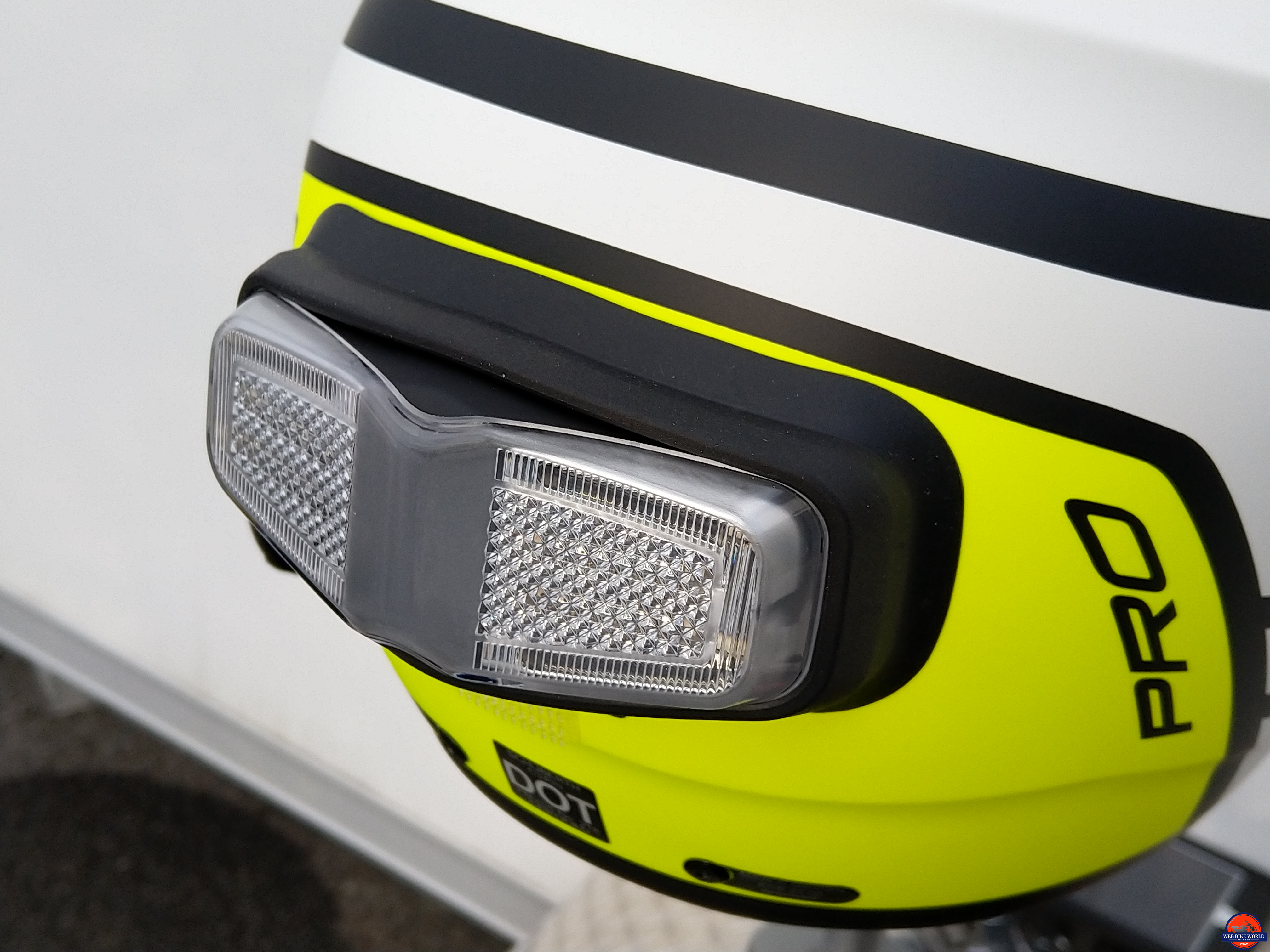
- First is the slightly curved helmet-mounted module with wireless transceiver and Red brake and Amber turn signal LEDs. White or Red outer lens covers are offered.
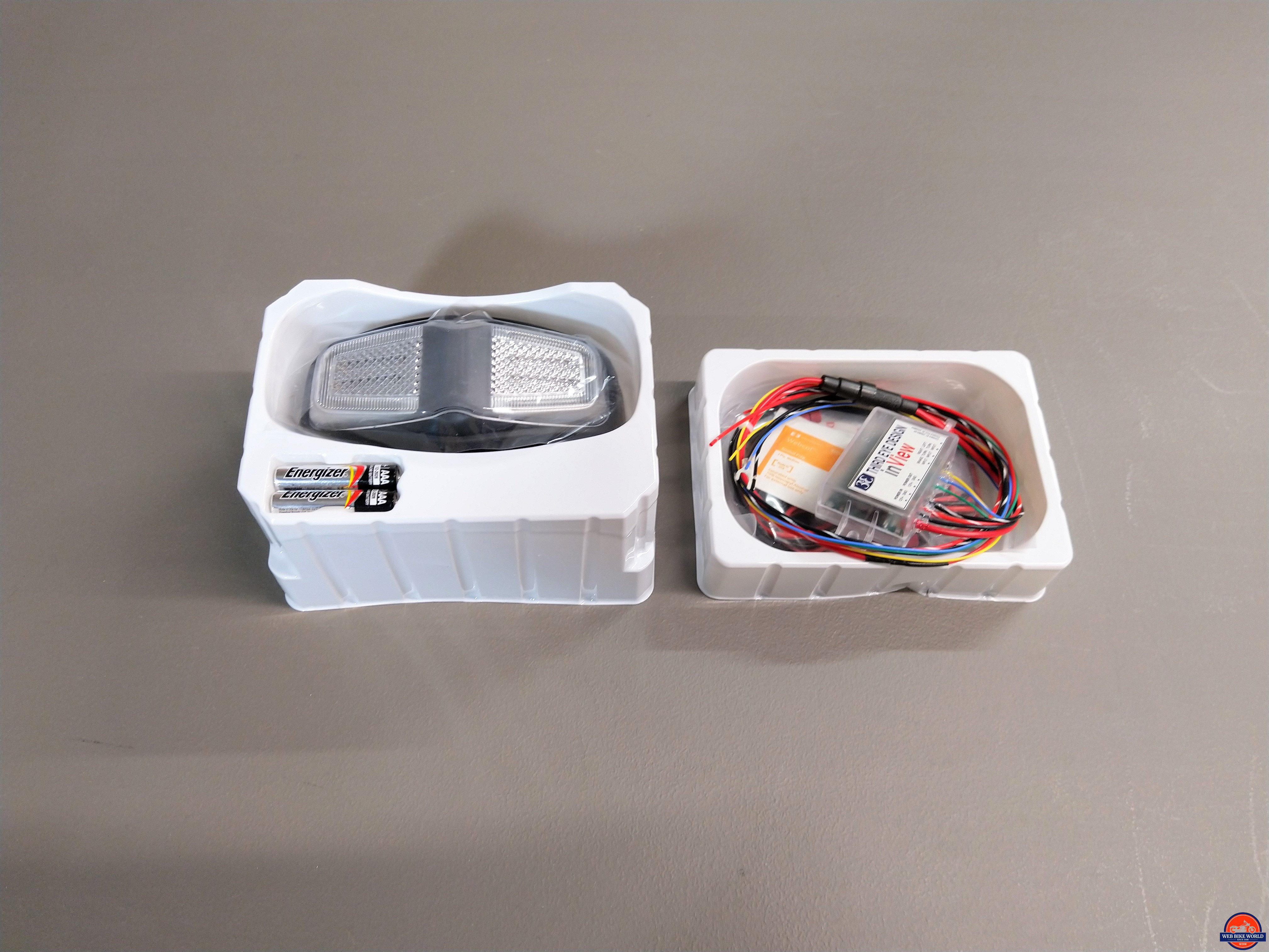
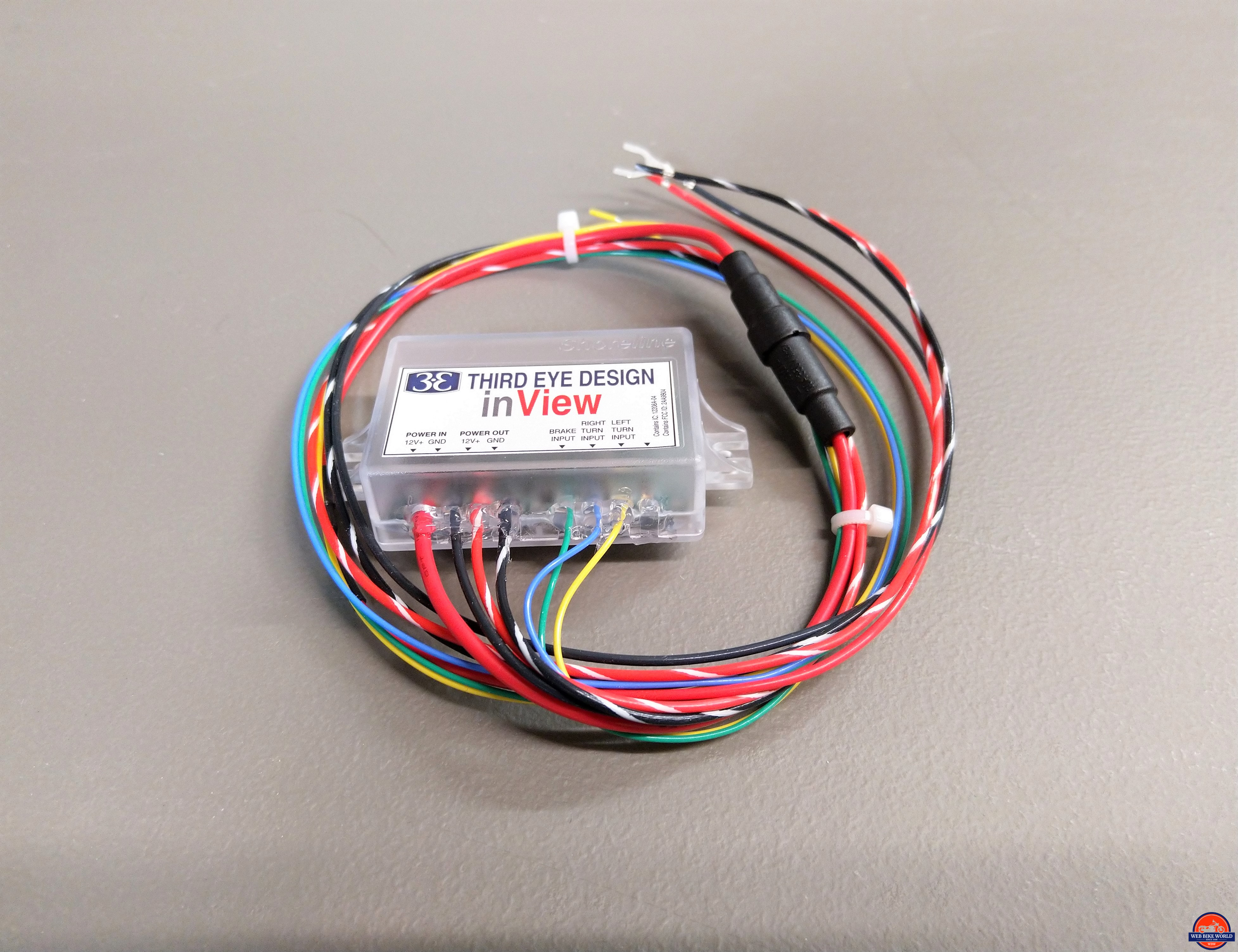
- A sealed translucent plastic module with multi-wire input/output harness, accelerometer sensor (for deceleration detection/dynamic braking measurement) and wireless transceiver form the second vehicle-mounted component.
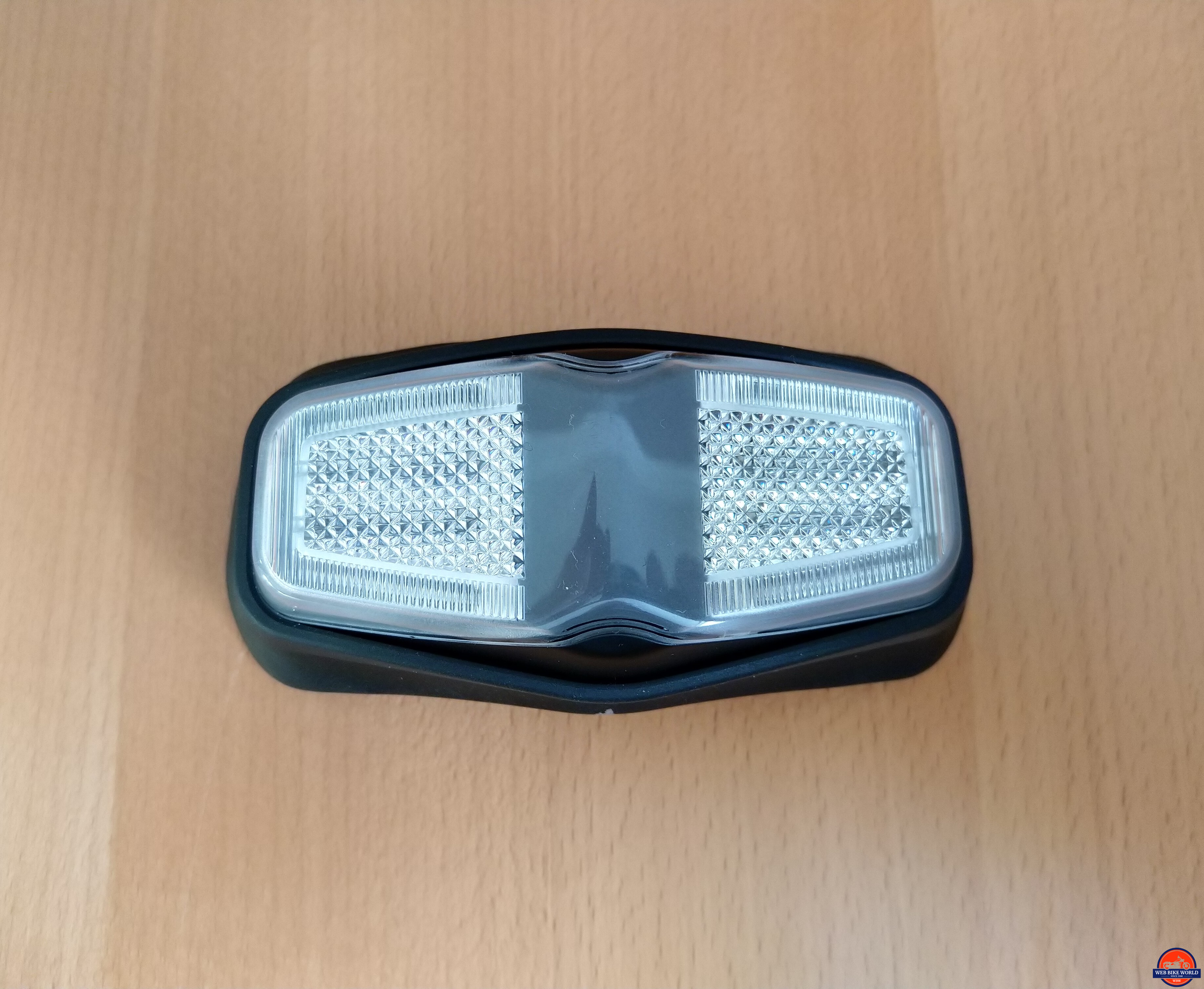
- The third component is a small Red LED module wired to output leads of the vehicle module providing a rear-facing auxiliary brake (brake activation and deceleration-based) output synchronized with the helmet LED module.
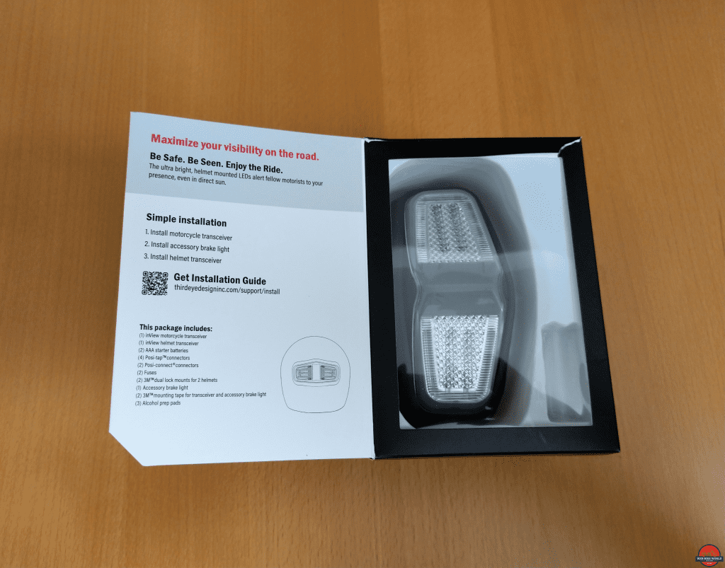
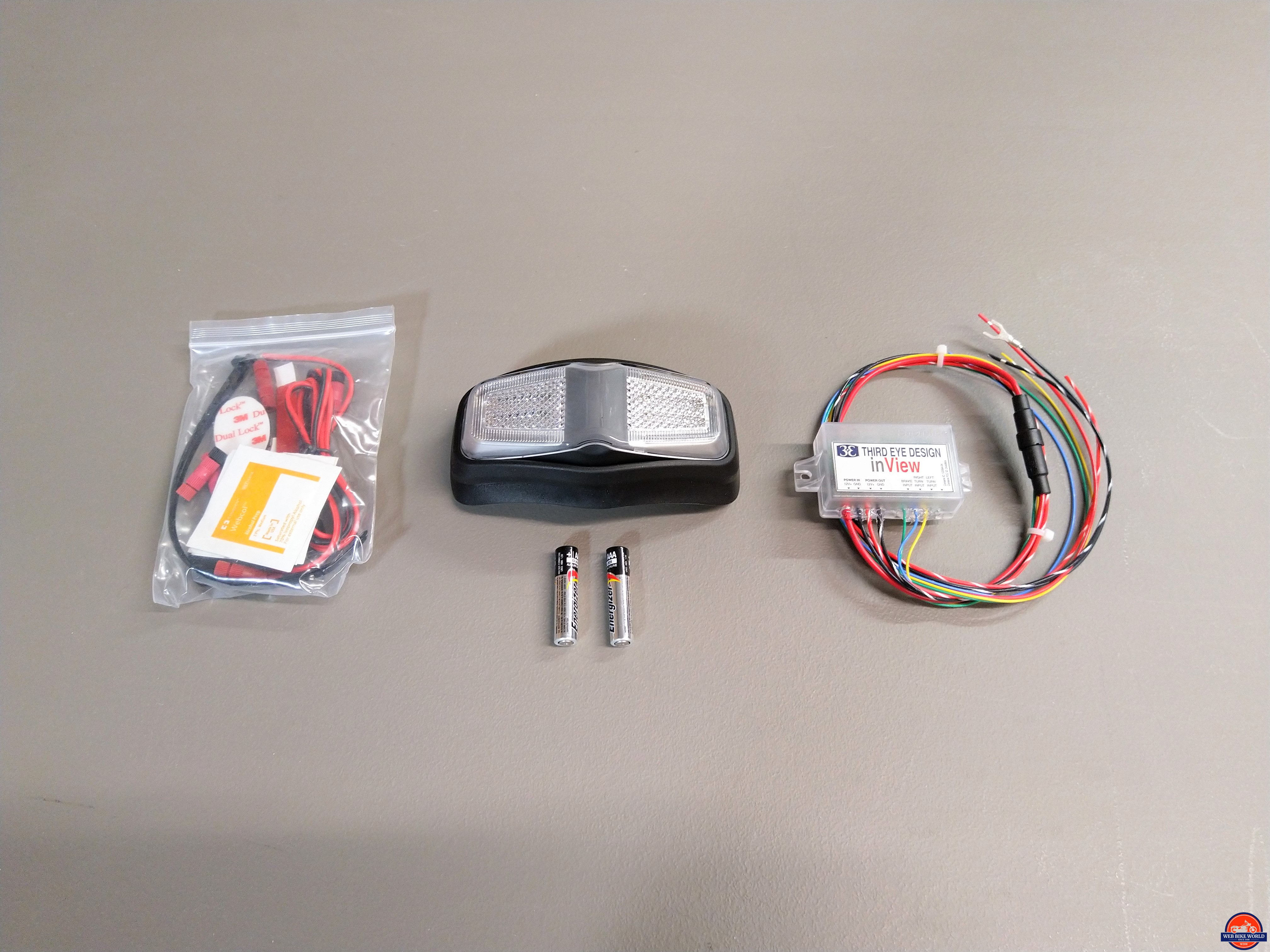
All the component parts and hardware pieces are neatly packaged in the retail box. Documentation – information sheets, detailed installation instructions and basic instructions for App use and updating, etc., is available for downloading at the Third Eye Design Support page.
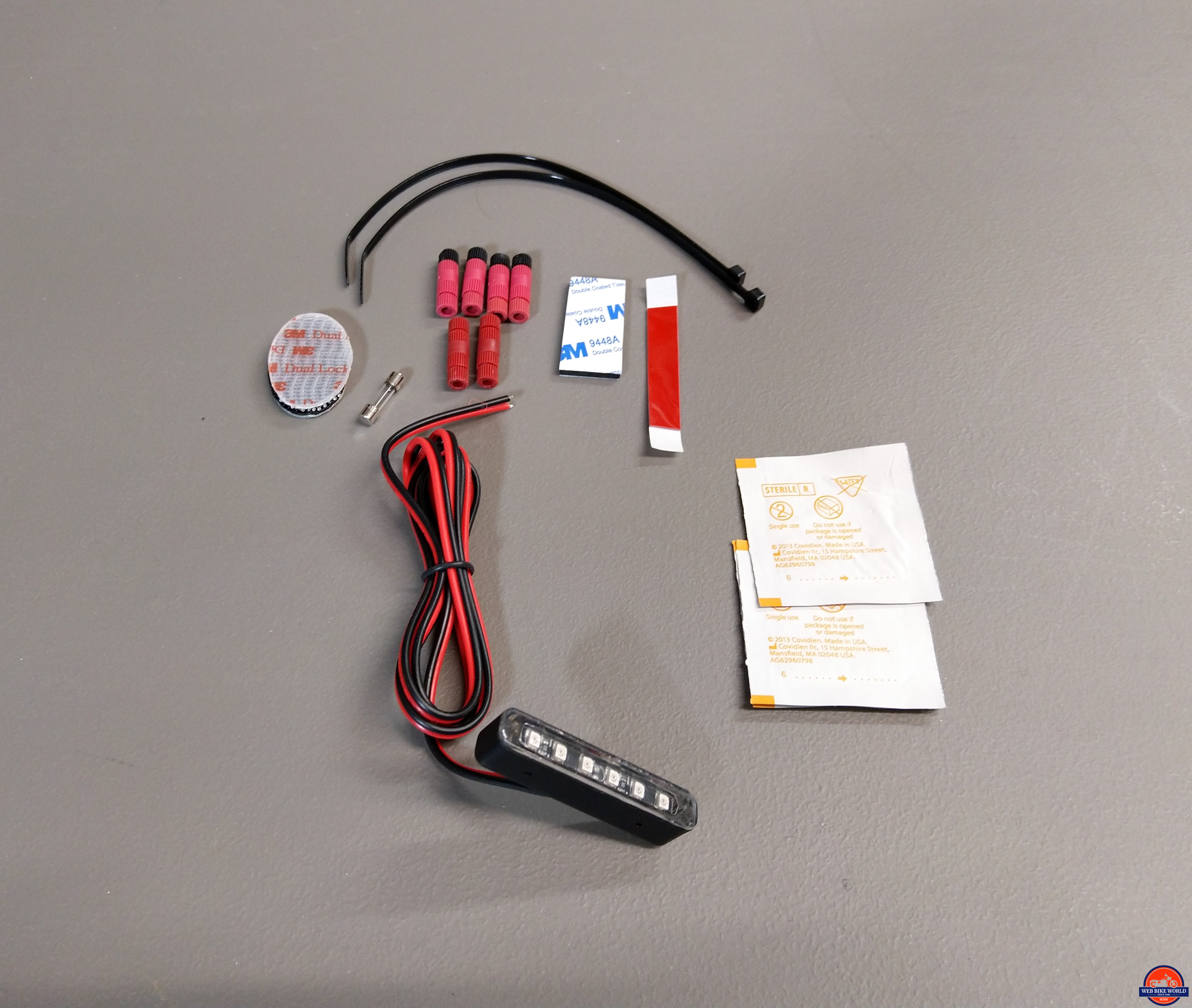
Kit Contents
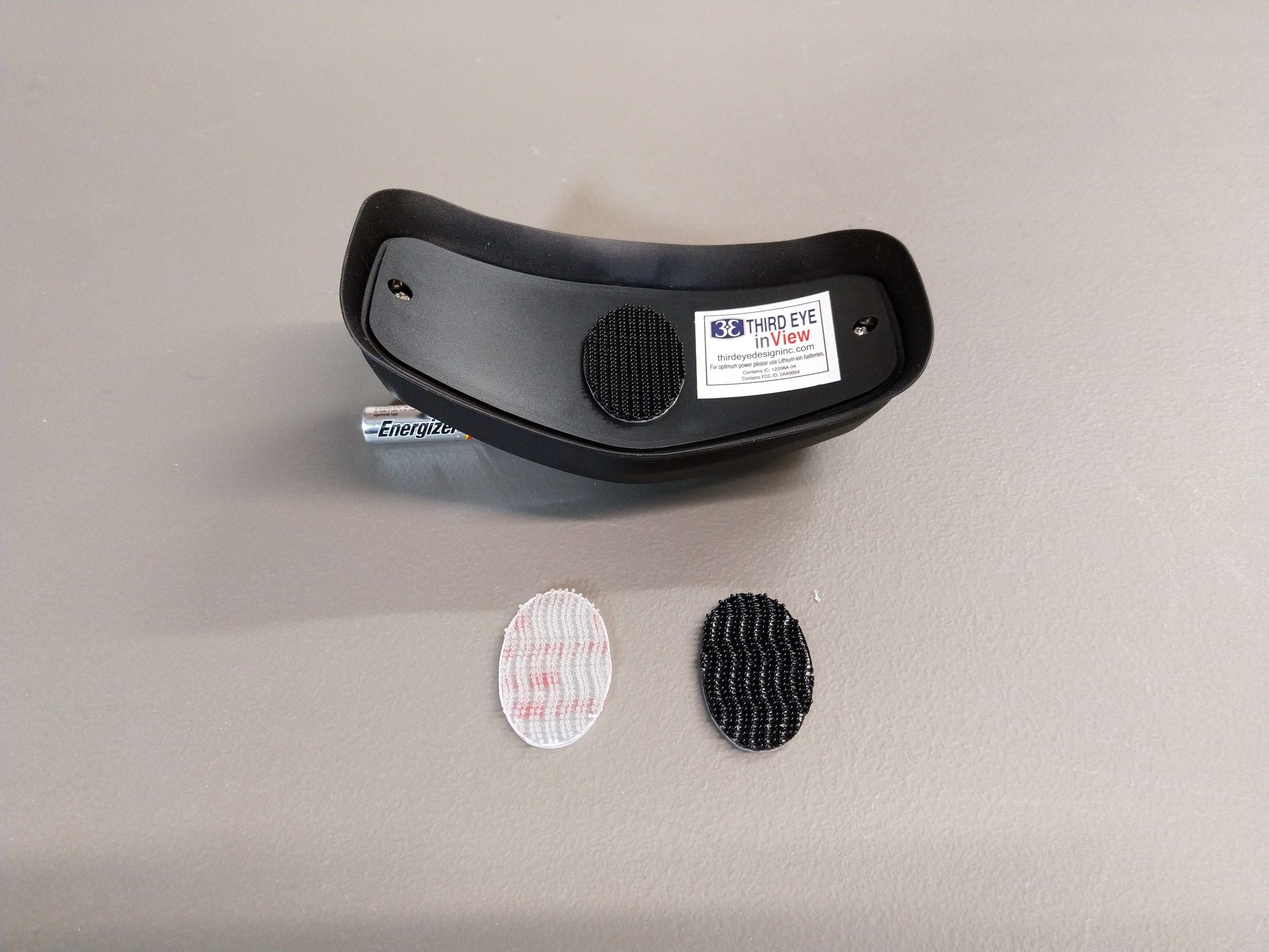
- inView Helmet Module with 3M Dual-Lock oval piece mounted
- Transceiver module (for vehicle mounting) with multi-wire input/output harness
- Accessory (auxiliary) LED Brake Light (vehicle mounted)
- Two AAA (alkaline) batteries, for helmet module
- Four Posi-Tap connectors (left/right turn, brake and ignition power connections)
- Two Posi-Lock connectors (auxiliary brake light)
- Two 1A wire fuses (one installed, one spare)
- Two 3M Dual-Lock ovals (mounting pieces for up to two helmets)
- 3M double-sided foam adhesive tape sections (for mounting transceiver module and accessory brake light), and
- Alcohol preparation pads
inView Functional Overview
Motorcycle Control Module – This is the controller or heart of the inView system. It also houses the accelerometer that provides the deceleration-based or dynamic braking feature of the inView system.
Input requirements are power, is supplied by a 12V switched onboard or power distribution system source, and connections from the OE brake and left and right turn signals. On the output side, the module provides wired output to the motorcycle-mounted auxiliary brake module.
Communication between the motorcycle and helmet modules is provided by the wireless transceivers integrated into both modules.
Helmet Module – The inView helmet-mounted LED module functions as an auxiliary brake and turn signal light unit. It is the ‘always on’ component of the inView system and is ready to go once the ignition is turned on and the vehicle and helmet modules connect via the wireless link.
The helmet module is also accessible via the App for output testing or to check for FW updates. When not in use, it goes to sleep to conserve battery power.
Auxiliary Brake Module Output – This output functions as the onboard auxiliary brake light and is mounted in (close) proximity to the OE taillight. Output from this module is synchronized with the helmet module.
Functional Outputs – When the rider activates the brakes and/or signal lights, the inView controller activates both helmet module and auxiliary brake module LEDs in sync with the onboard switching, although only the helmet module provides auxiliary signal light output.
The helmet located output that is well separated (vertically) from the lower-mounted OE and auxiliary brake outputs significantly increase the visual rear-facing profile of the rider and motorcycle combination.
Synchronized brake output from the helmet and auxiliary (brake) module also occurs when the deceleration-based or dynamic braking mode of the inView system activates after a threshold regarding vehicle deceleration is reached due to rolling off the throttle or downshifting.
Visual Messaging Correlation – Output synchronization between the OE brake and signal light outputs and the inView helmet and auxiliary brake LEDs sets the scenario for a real-time visual correlation between the onboard and auxiliary outputs to be made – this is key.
And even if the highest output (helmet module) is moving around somewhat (you know, that 360 situational awareness thing), the continuing synchronized output between the helmet and lower mounted motorcycle lighting should offset the (possible) negatives associated with helmet movement.
Mounting the auxiliary brake module close to (above or below) the OE taillight is another key ingredient, particularly regarding deceleration or ‘passive’ braking. When output from the inView helmet and auxiliary brake LEDs is synchronized, following traffic sees and makes the relationship between helmet and motorcycle mounted auxiliary brake lighting. Recognition, cognizance and learning.
This visual stimulus and output pattern messaging keep the following traffic aware, although the situation behind (directly or lane-related) is dynamic due to traffic flow changes, e.g. – turning a corner and entering a new multi-lane traffic stream or just changing lanes, etc.
Bottom Line Here – Following traffic needs to be provided with an ongoing and coordinated means to recognize the relationship between the helmet module and motorcycle outputs; the inView system provides this.
Having auxiliary lighting installed and managed properly is never bad; but if these same outputs are seen to be flickering, blinking or coming on without any seeming correlation to onboard lighting or rider/motorcycle actions, confusion can (will) reign.
I’ve had the good fortune to participate in or conduct testing of marketed or prototype auxiliary lighting pieces including deceleration-based braking systems. As such the scenarios above are very real. It is critical that visual messaging be clear, consistent, predictable and, legal.
inView Installation
Installing the multi-part inView system is straight forward, especially if the documentation is used. But if unfamiliar with this type of accessory or hesitant to undertake the work involved it should indeed be done by an experienced and/or qualified individual; don’t mess up a multi-part installation that could compromise the functionality of a safety-based system.
The downloadable Installation Guide and User Manual PDF is laid out in three parts correlating to the three main components and related wiring. The steps below are based on the inView instructions along with notes and observations made during installation.
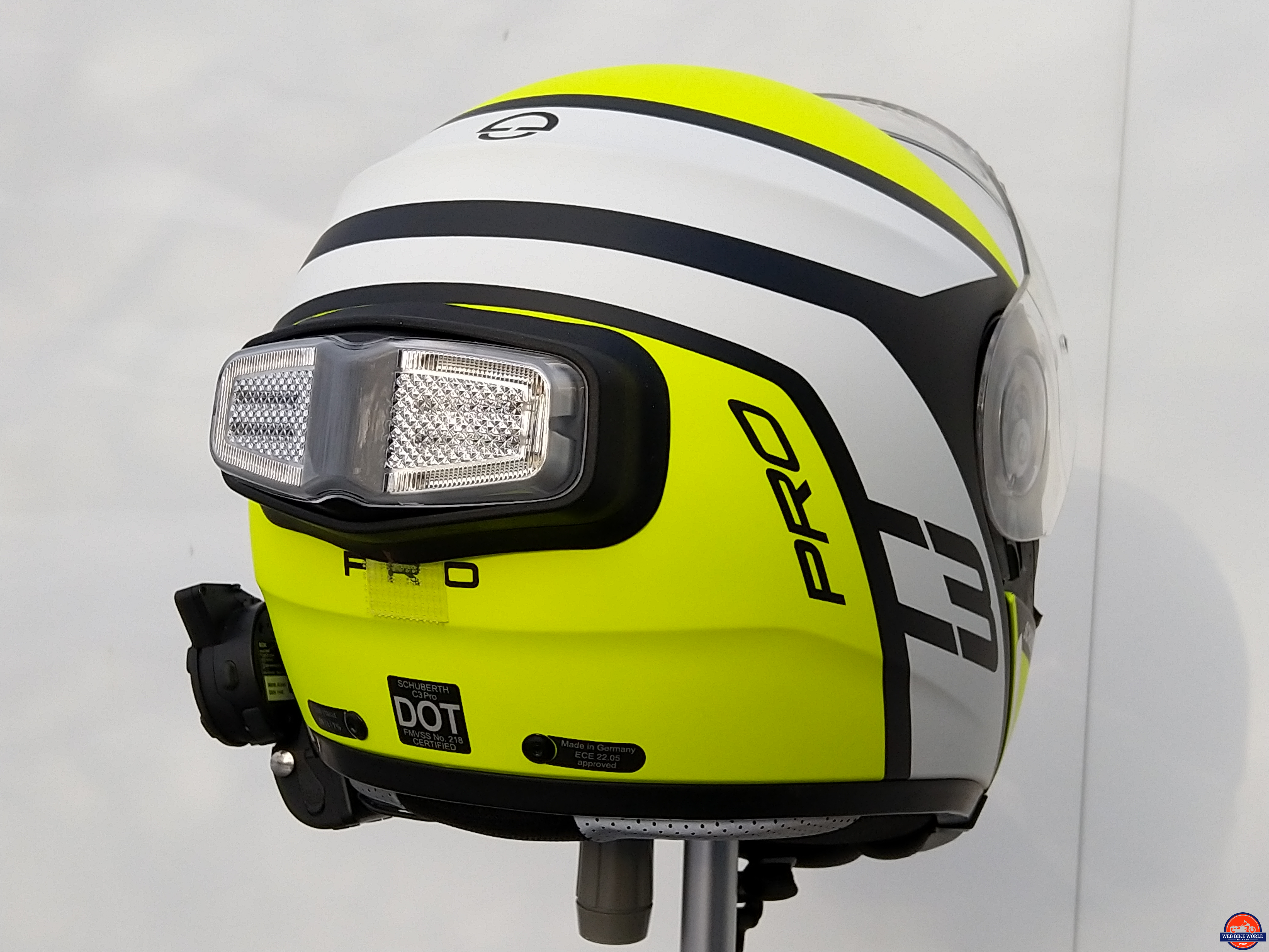
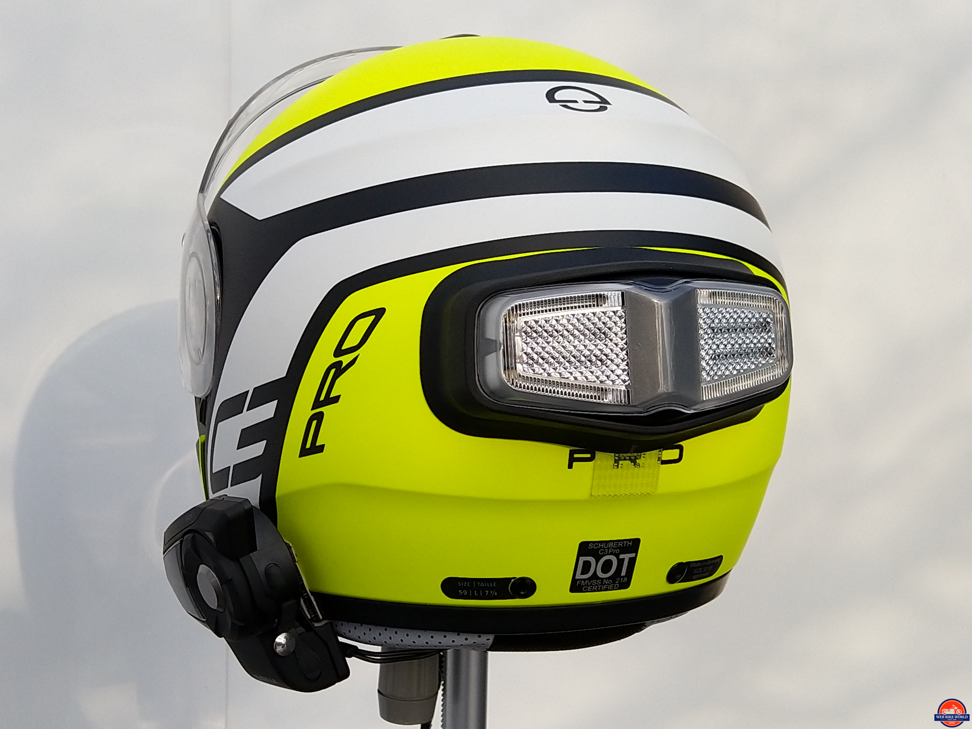
The (first) host motorcycle is the BMW F 850 GSA and host helmets (for now) are the Schuberth C3 Pro, Shoei J-Cruise II, and the new Sena Momentum EVO.
Bench Testing
The inView vehicle harness and auxiliary LED component are laid out on the workbench with a 12V switched source along with test harness (tail, brake, signal lights) connectivity from the motorcycle. The C3 Pro with an LED module sits eight feet away on another motorcycle.
Bench testing provides essential connectivity testing along with valuable insights into individual component connectivity and interaction at the system level. And, this activity initiates the formal information gathering and documenting of things.
In following the instructions and with only half a day or so lost in sorting out settings to get the (sometimes cranky) Nokia 7+ BT5 phone to pair and connect to both the vehicle and helmet modules, bench testing was informative and positive.
Installation Factors
A safe and secure mounting point; vibration (isolation); protection from the elements or onboard heat; and, keep the transceiver module from being hidden or obscured by large metal surfaces or major electrical components – both can cause degradation of wireless comms between the inView motorcycle and helmet components.
Installation Part 1 – Motorcycle Control Module & Harness
For this activity, the transceiver module and harness, three of the four Posi-Tap connectors, the larger 3M double-sided foam mounting tape sections and the alcohol prep pads (or another suitable cleaner) are needed.
This module is a sealed translucent plastic housing measuring 57 x 38 x 19mm (2.25 x 1.5 x 0.75in) with end mounting tabs. A seven-wire harness exits the front side. The module and pass-through points are sealed with silicone for water-resistant protection.
Location & Orientation
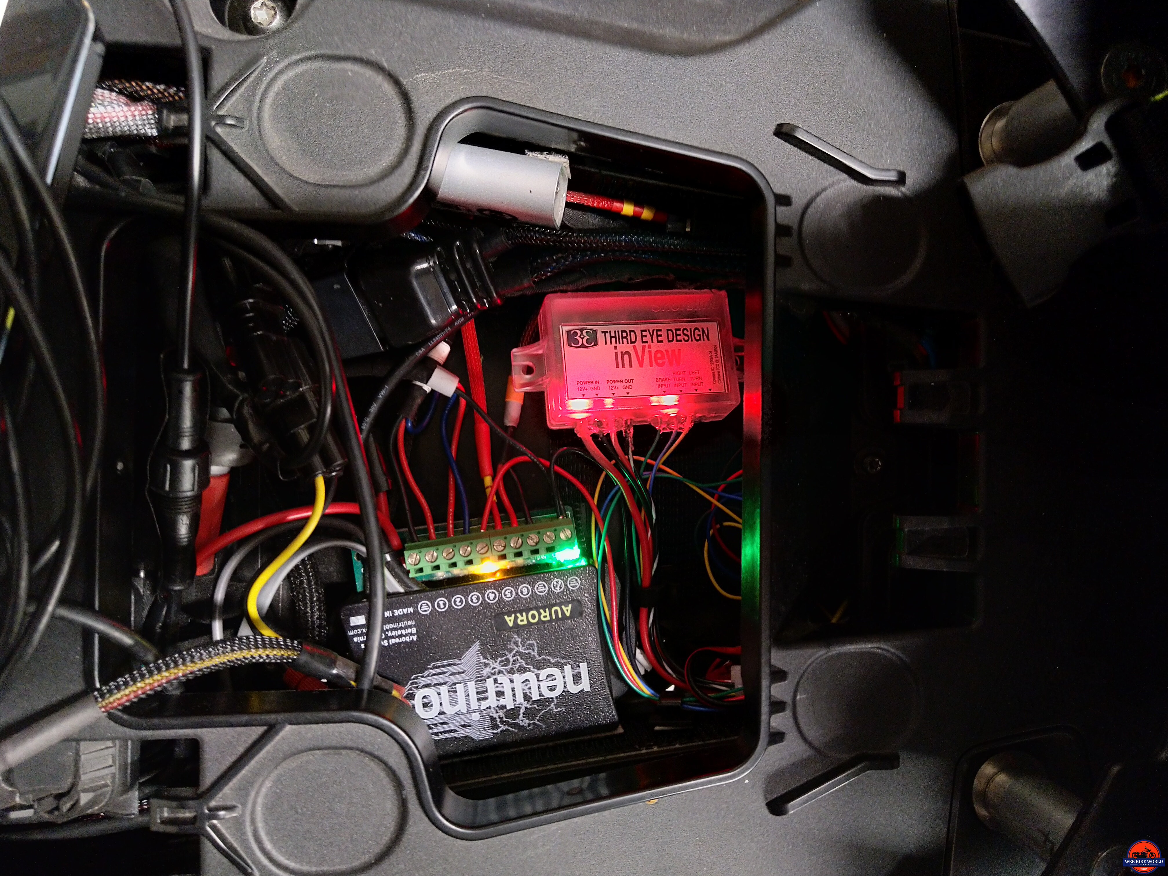
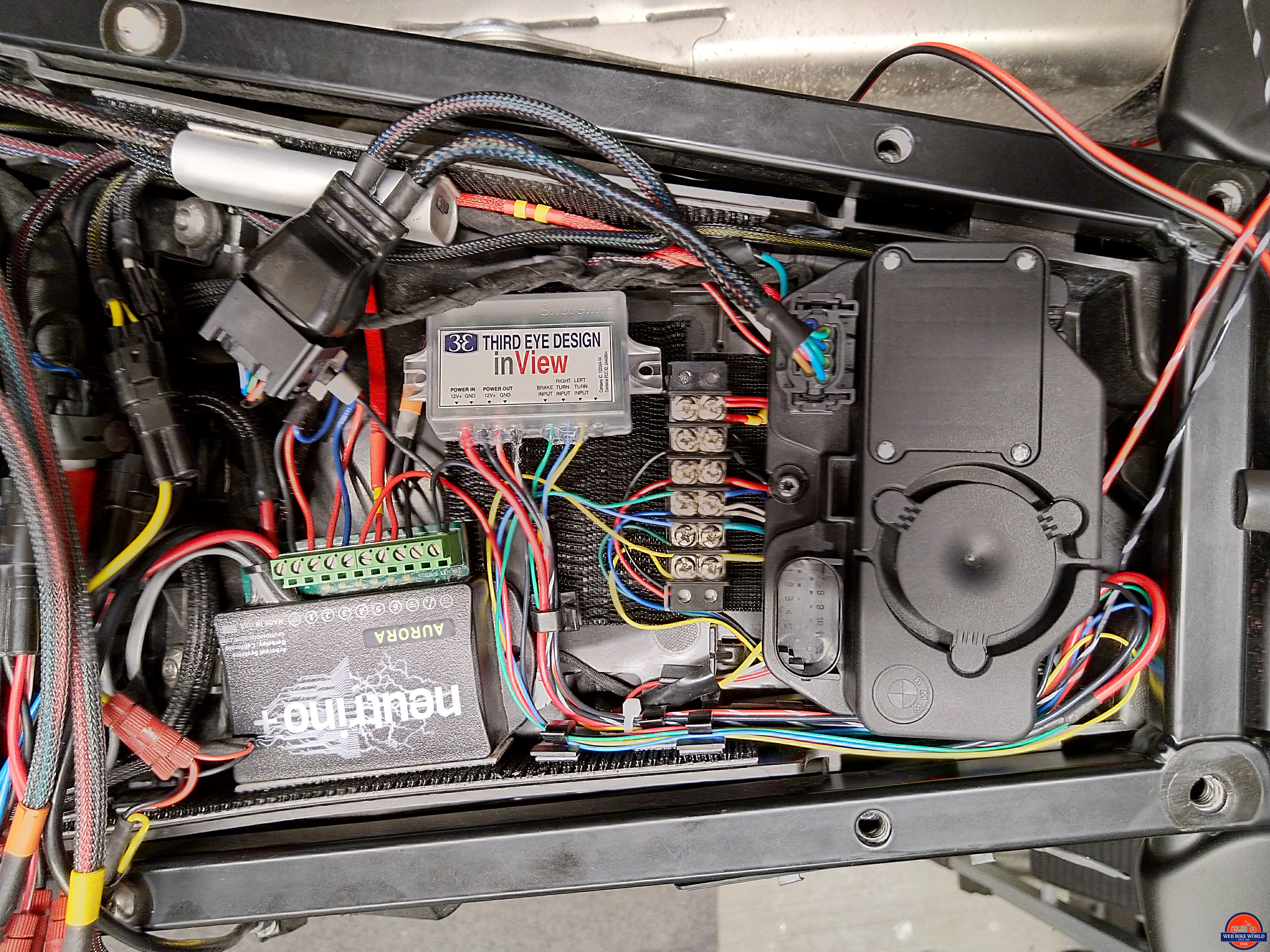
Best performance from the accelerometer feature is provided by mounting the module flat or as flat as possible on a stable surface. Thankfully there is just enough open space on the F 850 GSA to fit the module amongst everything else installed.
The sides and bottom of the under-seat ‘deck’ area have strips/sections of 3M Dual Lock mounted making it easy to install, adjust or remove electrical components as needed. With a small section of Dual Lock added to its backside, the inView module is snapped into place.
Harness Routing & Connectivity
Routing and connectivity of the harness leads is a variable between most installations and every user will have a different view of how it should be done; all good – just keep clearances and safety aspects first and foremost.

The long multi-wire harness exits the front of the module and heads for the left deck wall and is then run back behind the DWA (alarm) module and then looped back on itself so the wire ends sit where they need to be. I did not custom cut the harness as the system is going to be migrated to another motorcycle in the spring.
Module Power-In
After removing the 1A glass fuse from the in-line module and cutting the ring terminal off the black ground lead, the Red (+) and Black (-) leads connect directly to an available output and ground of the Neutrino Black Box+ Aurora mounted along the left wall.
*Note – although convenient frame ground points are identified as an option in the inView instructions, I don’t utilize them unless absolutely needed for expediency, preferring to use a direct battery connection or common ground block; it’s a choice.
Module Power Out
The striped Red and Black leads (pos and neg respectively) run back along the left wall and in between the alarm module and the rear crossover frame where they connect to the Red and Black leads of the inView auxiliary brake module with two of the supplied Red Posi-Locks (another option are Posi-Tite pieces, kept on hand here).
Test Mule Expediencies
Related to the 3M Dual Lock ‘floor and walls’ approach, the home fleet motorcycles have multiple accessories wired in – some short term, some long term. For expediency and to minimize wear and tear on often fragile OE wiring the applicable OE leads are accessed once with Posi-Taps with color-coded extension leads added to the other end.
These extensions are then routed and connected to terminals on the ‘input’ side of a 25A six-position double-row barrier strip with weather cover, mounted in an accessible spot (deck or sidewall). Along with the Brake, (Tail), Left and Right Turn Signal connections are one or two switched 12V power leads and a common ground (14AWG lead from the battery terminal).
For the inView installation with this layout the three color-coded inView module leads (Yellow = Left turn, Blue = Right turn, and Green = Brake) are connected to the respective terminals on the ‘output’ side. A more standard approach would have these connections made directly to the respective OE wiring using the supplied Red Posi-Tap pieces.
With the glass fuse installed in the screw-style holder (a small mini-spade fuse holder would be better) and another check of the wiring, pressing the Keyless Ride Power button and waiting an additional few seconds for the Neutrino Black Box (NBB+ Aurora) to activate its circuits in sequence has the inView vehicle module coming to life and completing its diagnostics.
Installation – Part Two
*Note: If tempted to skip installation of the auxiliary brake module – please don’t. This is an integral component of the inView system. When braking is activated, either by the rider or by the inView deceleration-based brake feature, it is (very) important to have a motorcycle mounted brake light that comes on in sync with the inView helmet light so that following road users see and (make) the relationship between the inView helmet light and (a) motorcycle brake light. This is the only (US) DOT recommended way to provide passive (deceleration or dynamic-based) brake signaling.
To install the accessory or auxiliary brake light module, the double-sided 3M tape, two Posi-Locks and one of the alcohol cleaning pads (or suitable safe cleaner) are needed. Other tools or aides may be needed depending on the routing of the harness.
Based on the note (paraphrased from the ‘inView Explained’ document) and as explained in the Functional Overview section, the most-effective layout for optimal visual correlation between the helmet LED, the auxiliary brake LED and (the OE brake light) is to mount the inView auxiliary brake module in proximity to the OE tail light (above or below).
The two-wire harness of the auxiliary brake component now housed in Flexo PET has routed into the back deck area thanks to a lower cut-out on the drop-fender section. This routing brings the harness into where the vehicle module connections await.
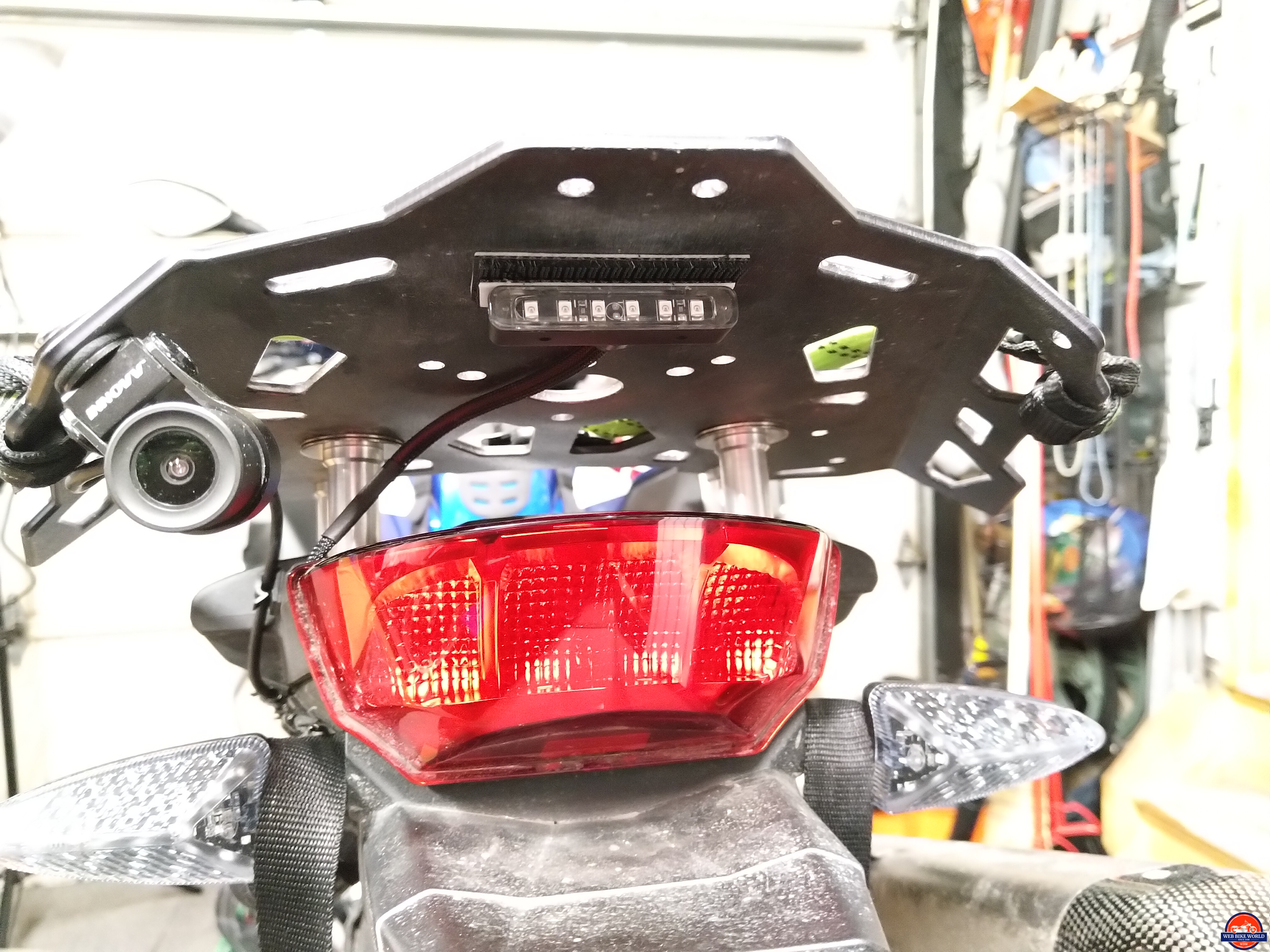
With these connections made and sealed with 4:1 heat-shrink, mounting the LED module to the underside of the Alt Rider luggage plate is next, to place the module above and in line with the OE taillight housing.
The more permanent 3M dual-sided tape is left in the kit and two 25 x 60mm pieces of 3M Dual Lock are cut, with one piece trimmed to a 12mm width to fit onto the module. After cleaning the underside area of the Alt Rider luggage plate and heating the 3M sections slightly with the heat gun on low, the larger section is stuck in place on the underside of the plate.
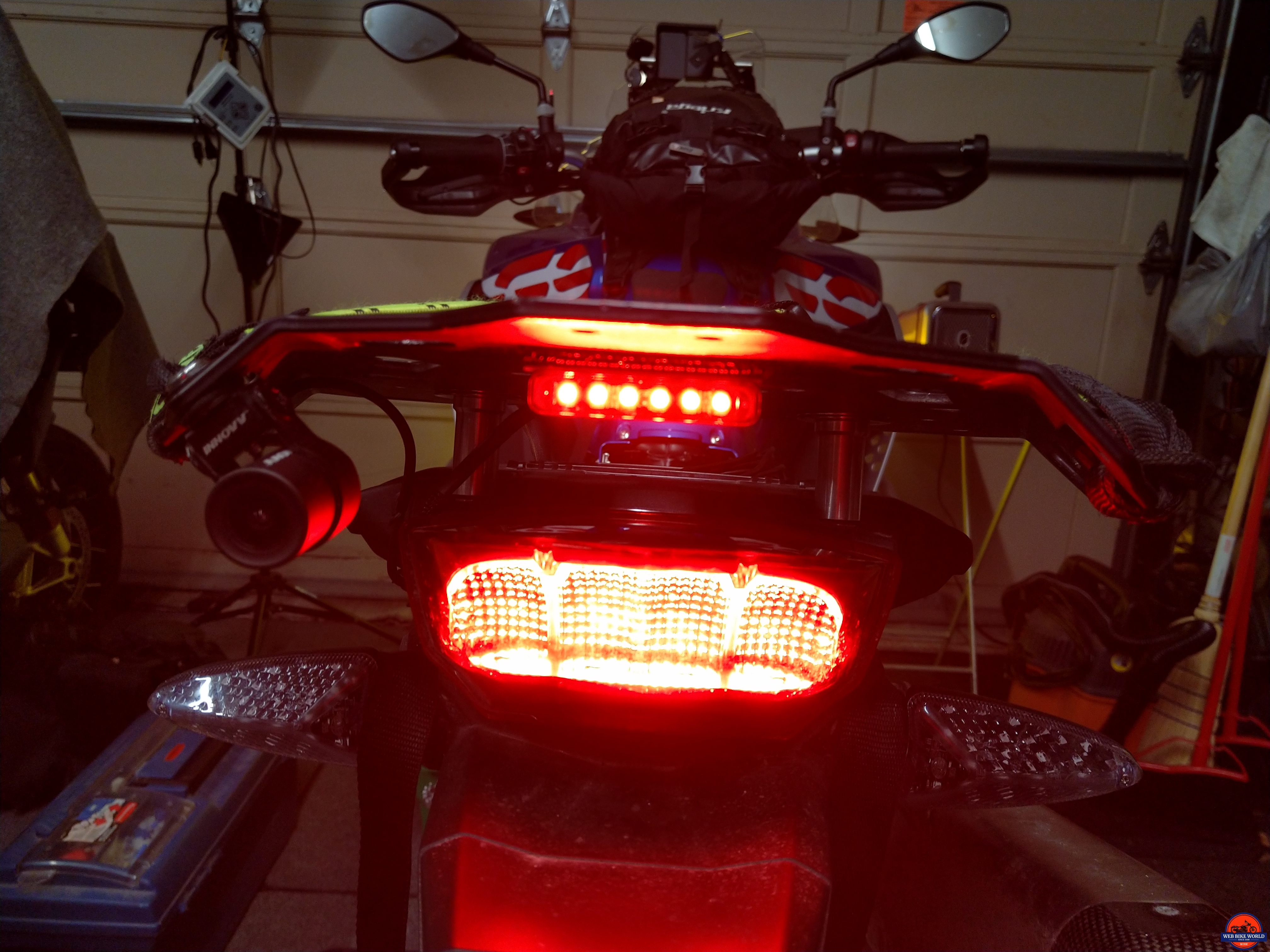 With a good initial bond verified the auxiliary brake LED module is snapped into place against the luggage plate – plenty strong for this lightweight component. The module sits 6.35cm or 2.5in above the taillight for a close (but not overpowering) output relative to the OE taillight.
Shopping Now? We Recommend:
webBikeWorld works closely with Amazon to provide our testers with quality products to review. While we have an affiliate relationship and receive a commission from items purchased, this addition comes at no additional cost to you. It is the primary way we pay for our site and reviewers.
Amazon
![]()
Installation – Part Three – Helmet Unit

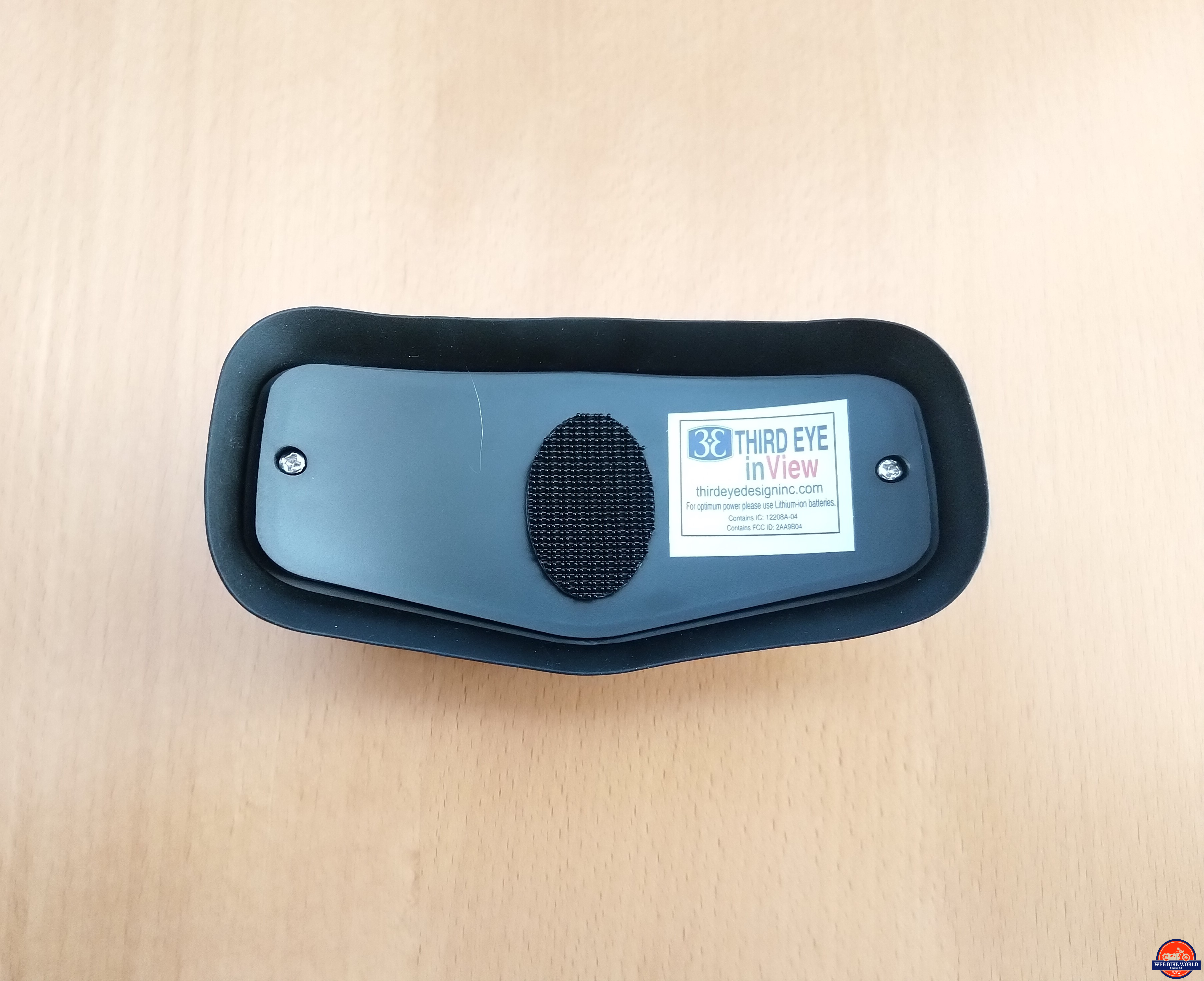
The helmet LED module, one of the 3M Dual Lock mounting pieces, two AAA Lithium-ion cells (the original alkaline cells provided were not installed) and one of the alcohol cleaning pads or suitable safe cleaner are needed for this activity.

Remove the curved backing plate of the helmet module (two Phillips sheet screws) and carefully (without losing the screws) pull or work the curved backing plate away from the housing and rubber skirt component, revealing the left/right electronics and center battery holder.
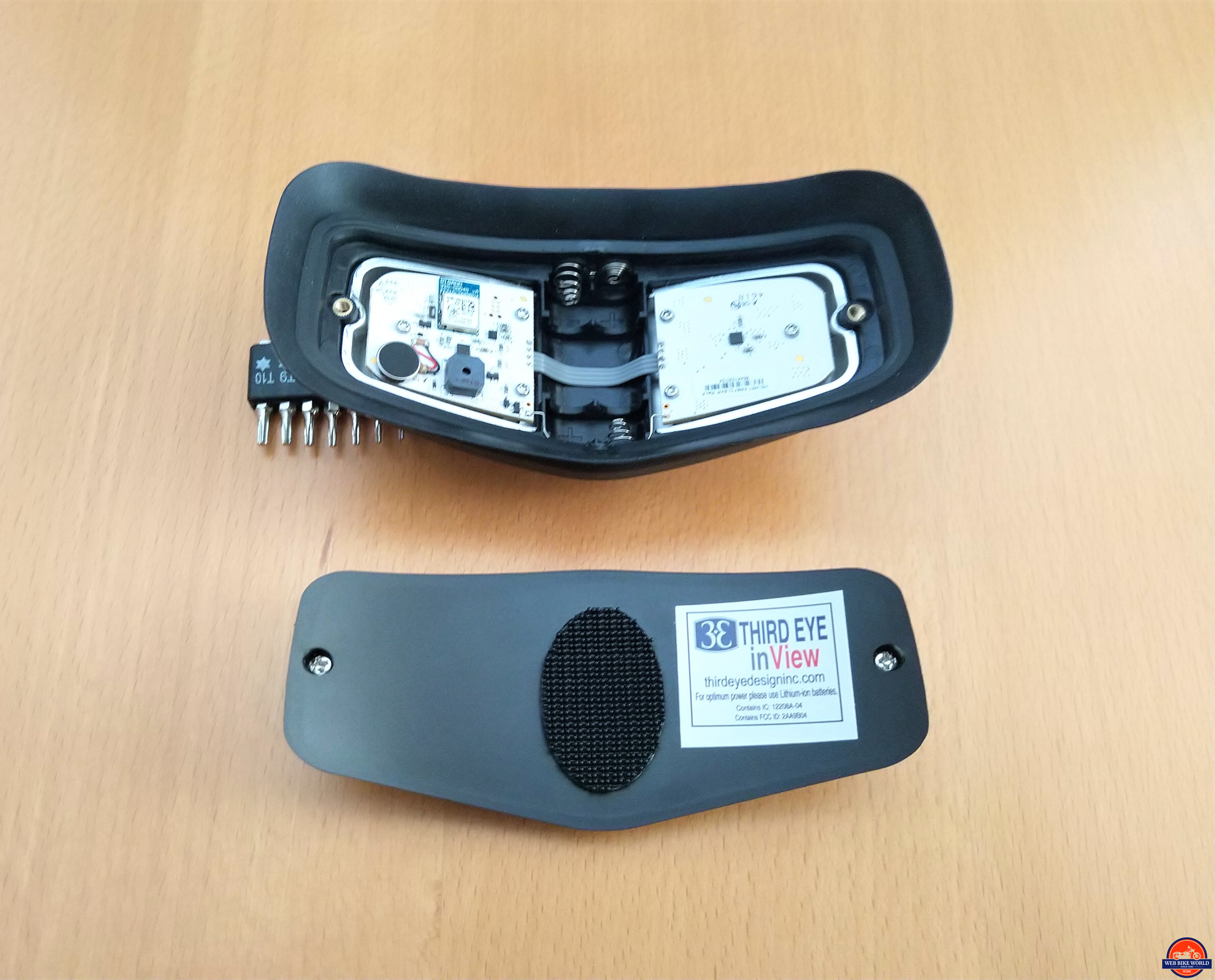
*Note: Before going further, you may want to mark in some discrete way the correct orientation of the module (just in case). Once the LED module is positioned for helmet mounting there are no visible external markings for reference purposes.
A fine-tip permanent Sharpie is used to add small reference marks on the inside of the housing (although the left and right electronics are good references) along with a small silver dot on the lower center of the rubber edge skirt for helmet mounting reference.
The back of the curved plate does have a Third Eye inView sticker on the right side for visual orientation of the curved backing plate. Besides, if the module is installed wrong, it will let you know once the system is activated…the beeping and flashing is hard to ignore.
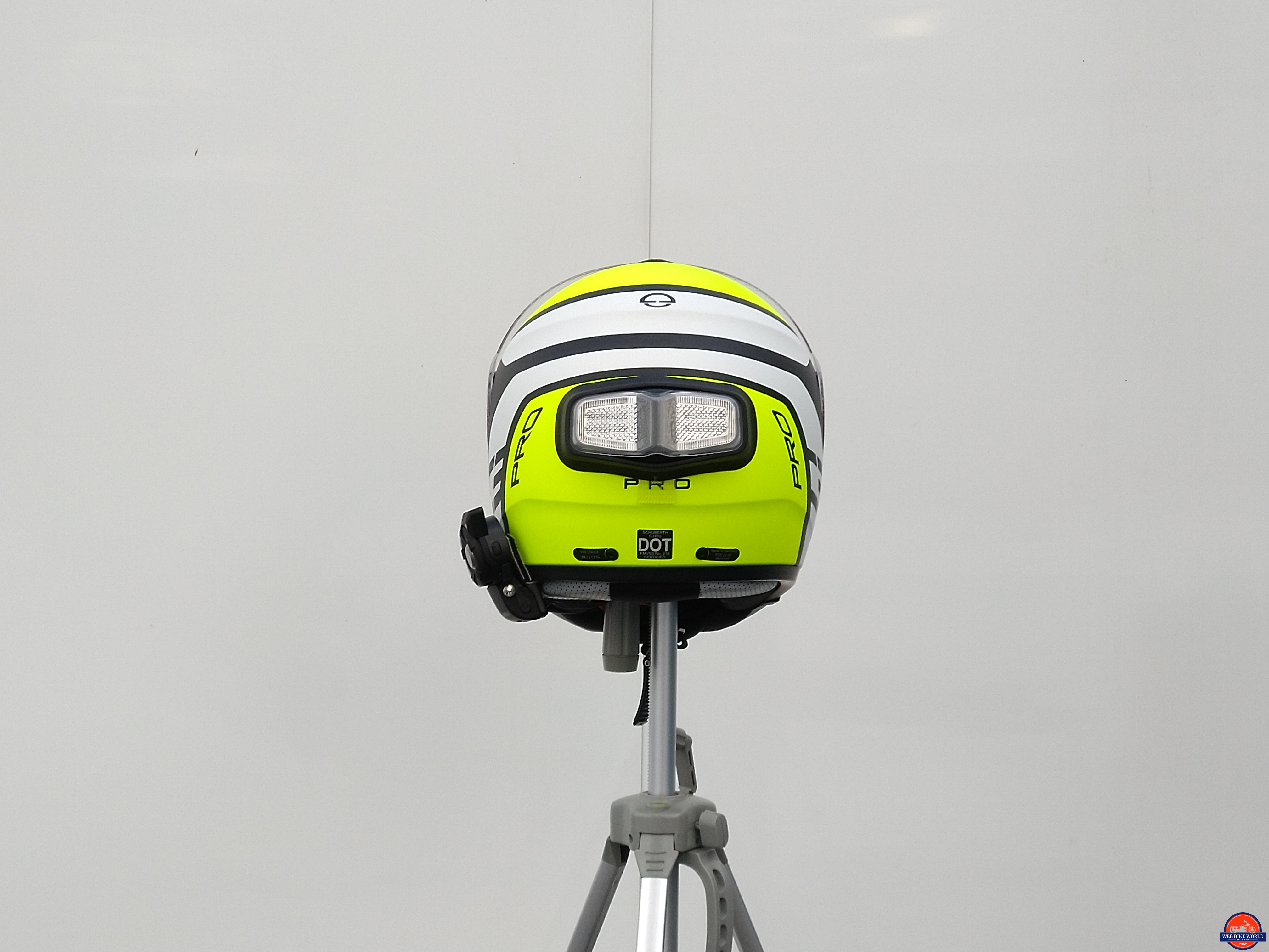
Placement
Even though output from the inView helmet LEDs provides a very good visual wide-angle footprint, it remains critical that the LED module be mounted on the helmet for optimal visibility regarding following traffic; rider, helmet and riding position are all factors.

Test Optimal Positioning With a Compatriot
A good starting point, with a compatriot (rider and/or driver) on hand to assist, is for the rider to prepare for and sit on the motorcycle as if going for a ride (feet or foot on the ground or center stand with feet on pegs) with ignition on to activate the inView system for testing.
With the compatriot standing to the rear, one or two vehicle lengths behind to start, activate the brakes and the signal lights in sequence while the compatriot moves out to varying distances and then does the same from left and right angles to emulate multi-lane traffic views.
When the compatriot’s memory banks are full… turn off the ignition and discuss the visual observations and, if needed (and possibly based on helmet), adjust the placement of the LED module up or down. For future helmet fitting reference, I made a paper template of the module’s fitted profile with alignment marks.
Once optimal positioning is determined the 3M Dual Lock helmet pad oval is mounted (12-24hrs curing time recommended) followed by aligning the module and snapping it onto the helmet oval. To remove the module, gently twist it to one side and wiggle it free.
Another recommended action before mounting – Have the compatriot sit in a four-wheeler and do the lane behind and lane left and right sightings. These ‘sighting’ tests, done for other auxiliary products or prototype devices always provide different ‘views’ or perspectives between motorcyclists, drivers, cyclists or pedestrians; enlightening and educational.
inView System Management & Firmware Updates
The inView iOS and Android Apps provide a single management tool for registration, updating, testing and operating the inView system. The App works the same way on both the iOS and Android platforms. Here are the iOS download and Android download links.
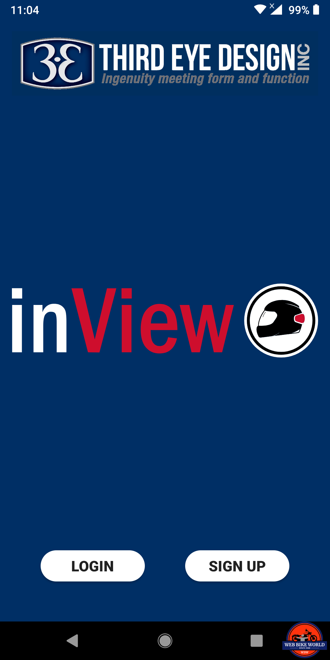
App Installation & Registration

With the App installed, open it and click ‘Sign Up’ to register the inView product. During registration, the user provides email and/or telephone information and a password required for Login purposes – allowing access to the App and management of the inView system/systems. Don’t forget the password…

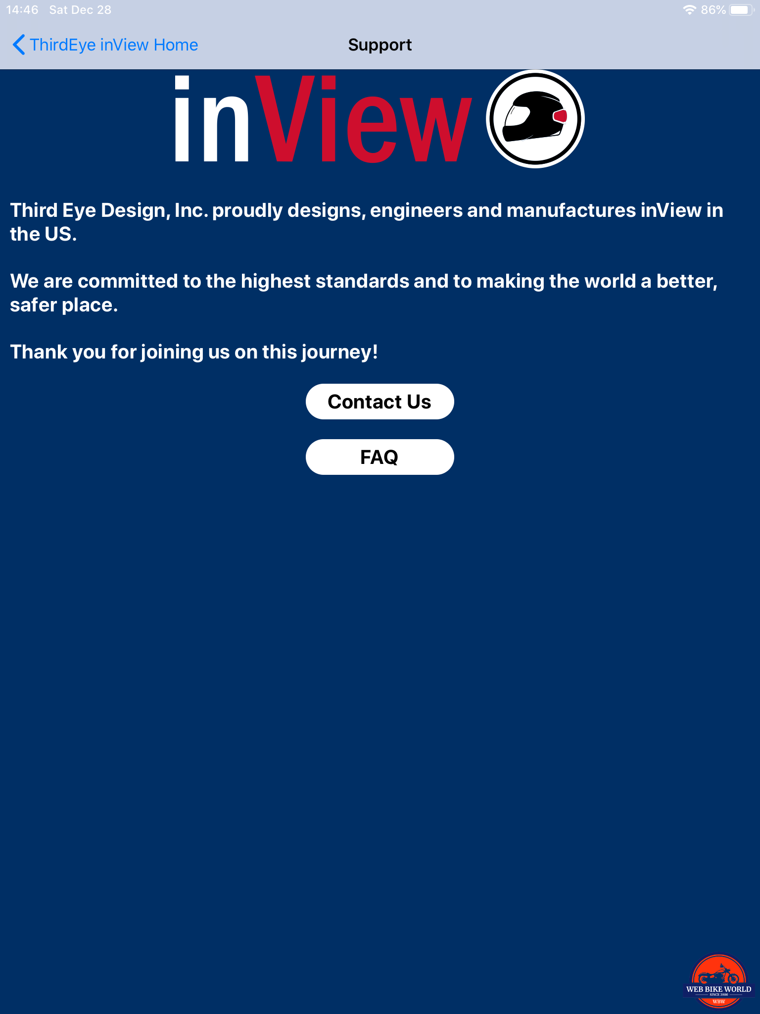
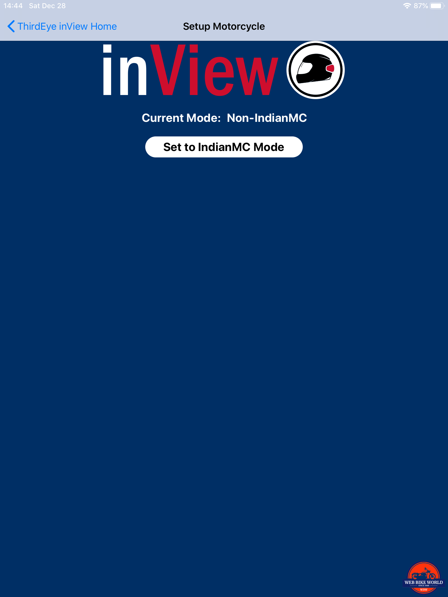
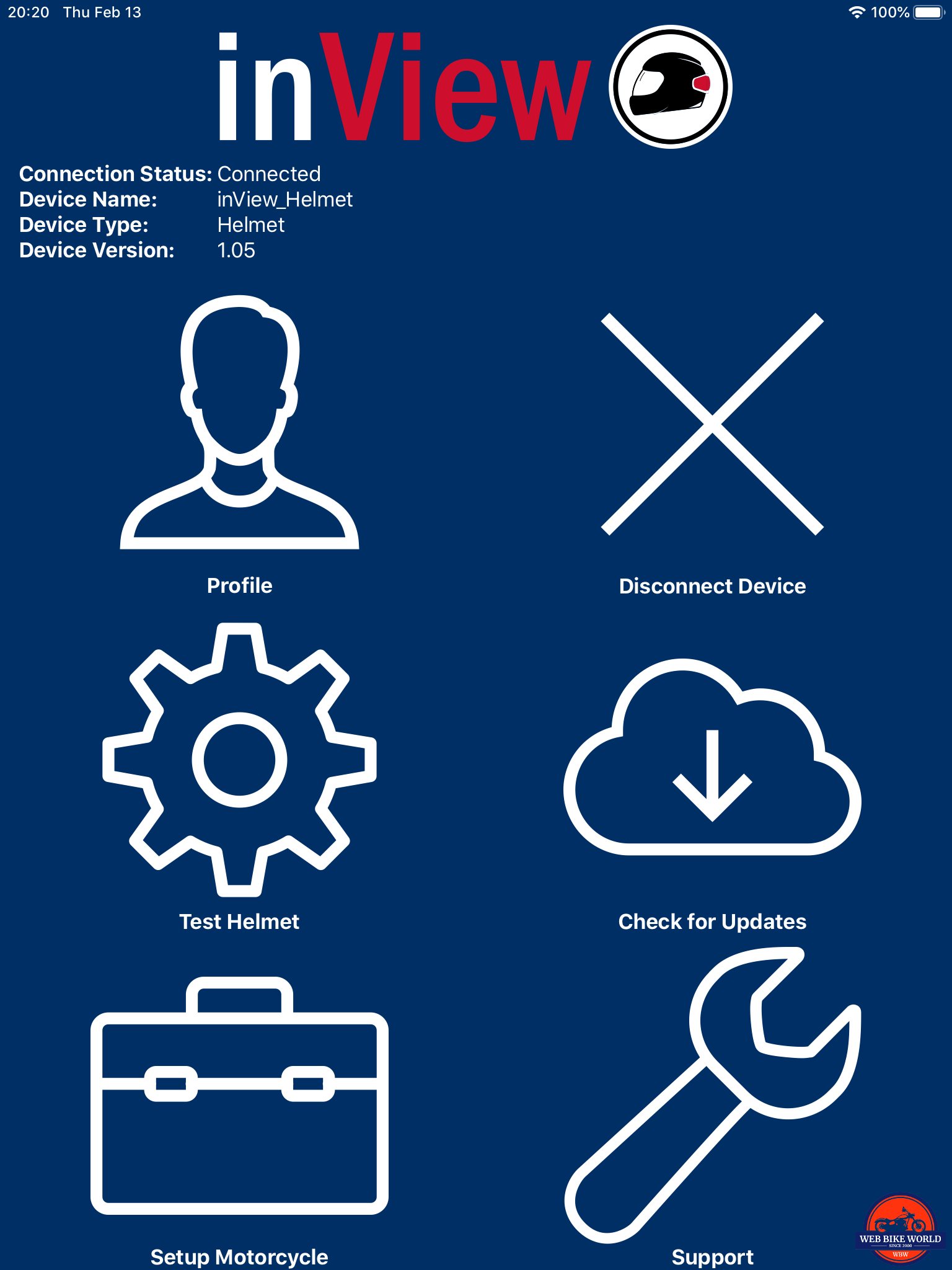
Once registered, the main menu screen comes up. From here users can update their profile, connect/disconnect from the motorcycle or helmet module, test helmet module output, check for module updates, contact support and as needed, activate ‘Setup Motorcycle’ that is a specific routine for Indian motorcycle owners.

*Note – make sure to ‘disconnect’ from one module before attempting to connect with another (only one connection at a time is allowed).
Connecting/Disconnecting
With the system powered and the user logged in to the App, tapping ‘Connect Device’ brings up the Connection Screen. After about five seconds the ‘inView_Motorcycle’ is listed – selecting it and waiting a few seconds has the main screen open with module connection info displayed just below the inView logo.
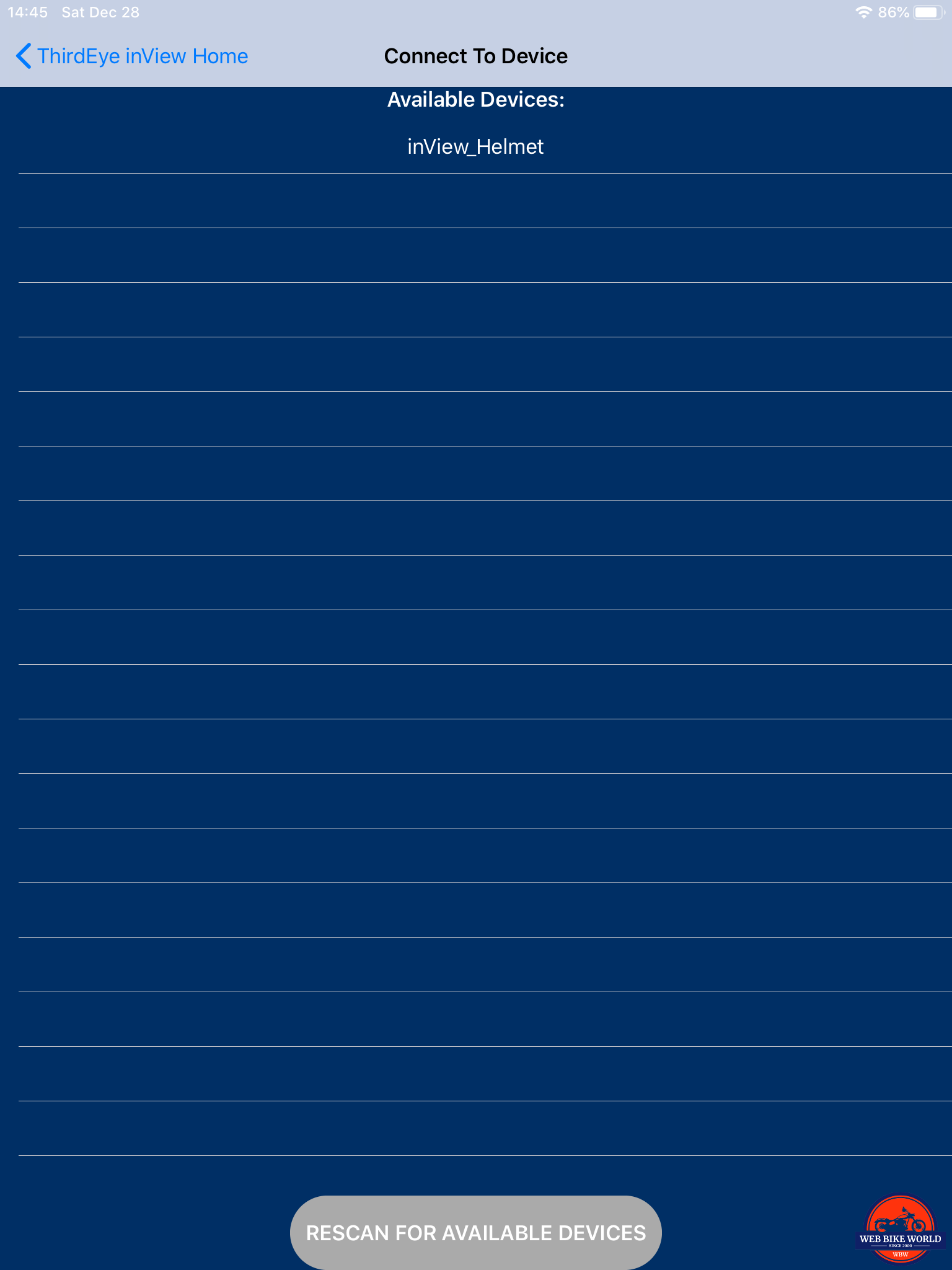
Issue – In disconnecting from the motorcycle module, attempts to access the helmet module were not successful, hmmm. After recycling everything, including Bluetooth on the phone and then getting the ‘inView_Motorcycle’ connection up, disconnecting from it and initiating the helmet module routine worked, although it took about ten seconds for recognition to occur.
These connection delays seem to be the norm, although sometimes the connections are made within two to three seconds. The Third Eye Design team is aware of this and some output switching issues; pending firmware updates should address things.
Connecting to the helmet module provides more action than the usual quick and (silent) vehicle connection. When the helmet connection is made, it is announced by a double flash, double beep, and vibratory tone. Disconnecting results in a single beep, single flash, and another tone.
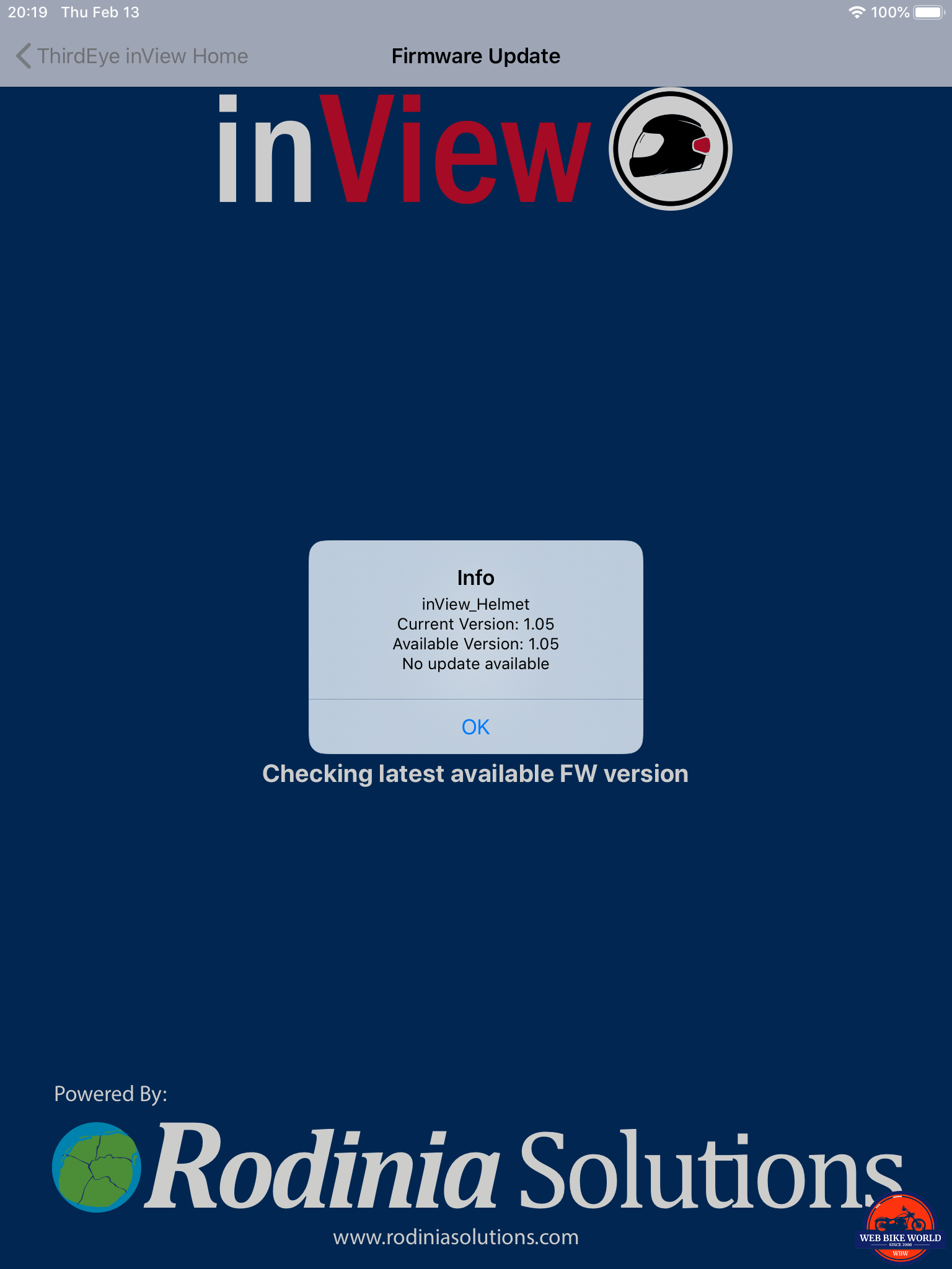
Updating Firmware & Helmet Module Testing
Thanks to the Third Eye Design team the unit provided for this review had the latest firmware. Users have a one-tap ability to ‘Check for Updates’ – just remember to disconnect from one module before moving to the next one.
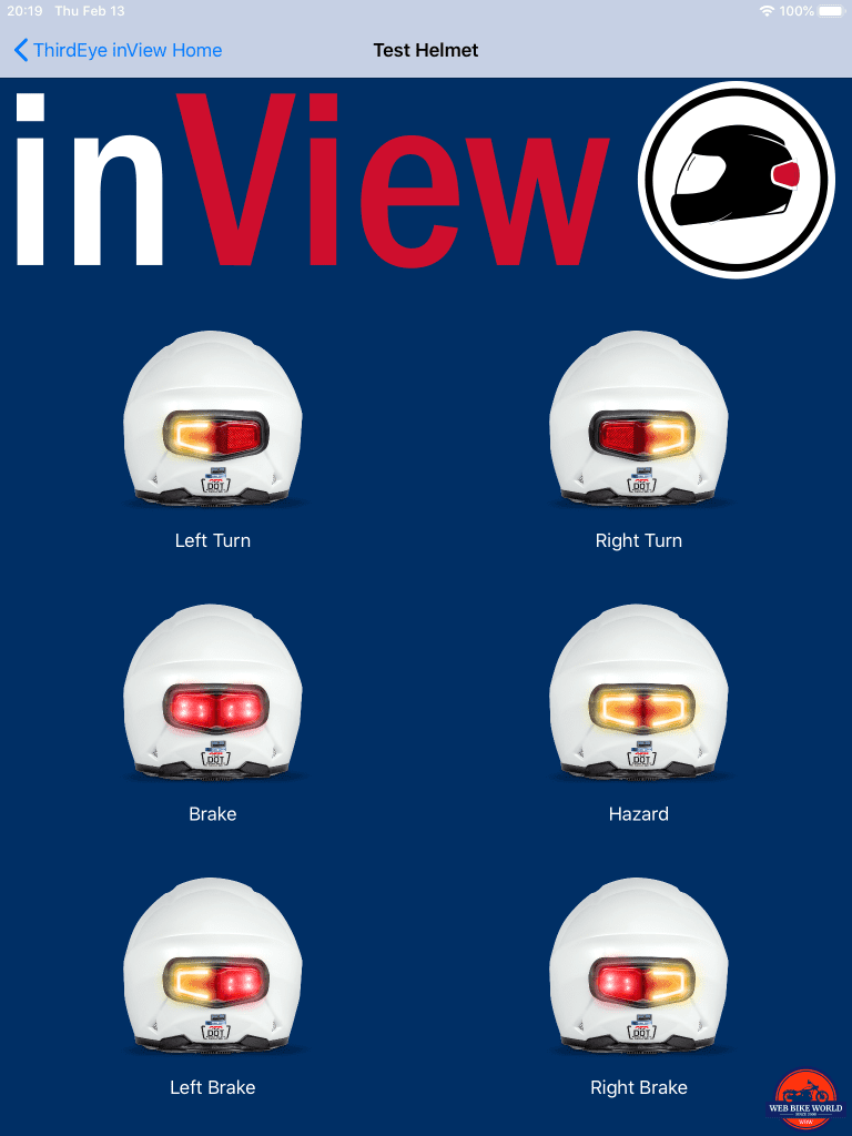
To test helmet module output, connect to that module and tap the ‘Gear’ wheel to bring up the Test Helmet screen. Touching any of the six activation icons tests each of the output functions separately.
Watch the video below to see the helmet module output test in action using the App:
And if the helmet module brake lights are flashing, it means the batteries are getting low – replace them for optimal performance.
Initial Observations
The inView Helmet Brake and Signal Light System took a bit of time to bring to market, but in a very short time, it has gained lots of kudos from users along with many positive reviews. It is truly a product we should have had a long time ago…
But thanks to Third Eye Design, the product is here, available and growing a large user base, with Twisted Throttle recently taking on North American distribution. The product also won the prestigious “Best Safety Product” award at AIMExpo 2019.
Initial use confirms that the inView system works as advertised, with its three connected (wired and wireless) components forming a smooth functioning set-n-forget system; with the ignition on and the modules synced (the helmet module is ‘always on’ per se), the system is ready to go.
Some initial ‘nits’ have emerged. The first regards the single 3M Dual Lock piece mounting – it works but it could be a bit stronger (larger) and additional mounting points (left/right) could be good to address helmet shaping/styling; more on this in the follow-up.
Relatedly, the pliable sealing skirt serves function and form, but increasing its coverage surface would be good, especially for helmets that have less than oval surfaces and styling/spoiler lines.
Finally, a switching lag of around 250ms is evident with helmet module output typically with brake activation and release; this issue is observable on some posted videos as well. I’ve seen this with other wireless systems; pending firmware updates should mitigate this issue.
Subject to getting riding time logged to gather more functional information along with more feedback from road users, the First Look Impressions are all positive.
The inView Wireless Brake and Turn Signal Light by Third Eye Design is an innovative and universally installable, set-n-forget safety-related product that bears a very close look. Stay tuned for our spring follow-up.
Pros
Cons
Specs
Shopping Now? We Recommend:
webBikeWorld works closely with Amazon to provide our testers with quality products to review. While we have an affiliate relationship and receive a commission from items purchased, this addition comes at no additional cost to you. It is the primary way we pay for our site and reviewers.
Amazon
![]()


I’m surprised that you did not mention a possibly better product – https://www.indiegogo.com/projects/brakefree-the-smart-brake-light-for-motorcyclists/x/18821792#/
You are right that this product was not mentioned…my omission as I am aware of it, and other products that tried to come to market or may make it to the consumer market. But by the same token, its not yet seen as widely available (I stand to be corrected on this as applicable); in having tried for almost two years to make contact the company or even pre-purchase one. Long reply made short – if one can be purchased or provided, it will definitely be reviewed. Bruce