

Dispatch 1 Review
This section describes how to initialize the Dispatch 1 system and how to connect the devices and accessories that will be powered and managed by the system.
While my observations on the Dispatch 1 system are few, there are a few issues that could and should be addressed to further enhance this new system and I will discuss those also.
Initializing the Dispatch 1 System
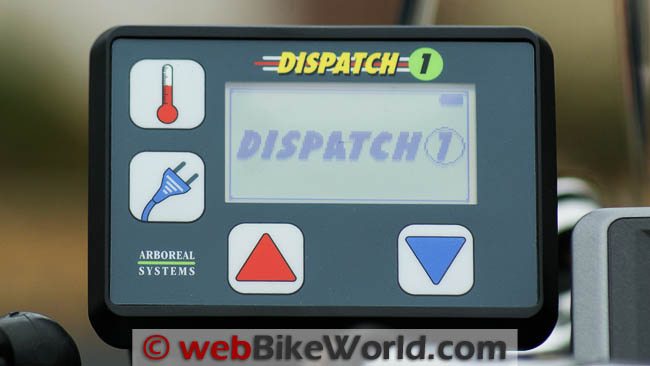
Where are we…oh yes, Florida! Under a clear, cool sunny winter day in Florida I push the upper left Thermometer button on the Dispatch 1 controller and release it.
The Dispatch 1 logo displays on the LCD screen while the controller searches for the distribution module via the wireless capability.
Within the space of a blink, the radio link is made and the default screen appears.
This is the environmental screen, which displays three data lines: time and date; battery voltage; and the ambient air temperature.
The setup screens on the Dispatch 1 system include:
Time and Date; Port Memory; Screen Contrast; LCD Backlight; Default Status Screen; Temperature Readout; Voltage Alarm; Set PAN ID; SN and SW Ver; Trigger Config (configuration); Heat & Output Screen Return; and, Exit.
Hmm, the temperature reading is 41F (5C) — no wonder it feels cool! Resisting the urge to play (what, me?), I dutifully follow the manual and work through what should be the next step after initially configuring the environmental screen.
Initializing the Dispatch 1 System: The PAN ID
This next step is quite important and should not be overlooked. What this step does is allow the user to assign the Dispatch 1 system a unique identification code, called the PAN ID.
Simply put, if operating in an environment where other Dispatch 1 systems are within Zigbee radio range, your system remains under your control.
Press both the red and blue buttons momentarily and then release them, which brings up the initial setup screen, the first of several.
Note: Since the initial release of the Dispatch 1 system, software changes have been made so differences in configuration options can vary. More information on updates is provided in the Conclusion section.
On to the PAN ID. Step through the setup menu screens using either the Red or Blue buttons until the Set PAN ID screen appears.
Press the Plug button and toggle through the letters and numbers, again by pressing the Red or Blue buttons; any combination desired can be used for your unique system ID.
Once you’re happy with the PAN ID choice, press the Plug button to advance to “Save” and press the Red button to save the settings. The system will (instantly) reboot with the new PAN ID now resident in both modules. Playtime has arrived.
Where to Buy Dispatch Motorcycle Power
See More: Motorcycle Intercom, Motorcycle Accessories, Motorcycle Helmets
Setup Screens
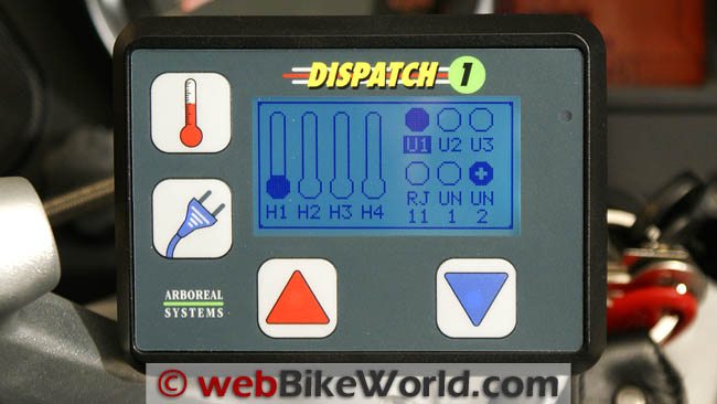
The default sandbox or view is the main environmental screen that shows real time data refreshed about every 500 milliseconds.
If you want to view only one data set in a larger screen mode, press either the Red or Blue buttons to toggle through the screens.
A good setup exercise, described in the manual, is to activate one of the circuits — this being one of the heated or heating outputs. Press the Thermometer button and release it, this takes you to the Action screen.
The H1 thermometer will be blinking, signifying that it is ready to be used.
To activate and increase the temperature setting either press the Red button repeatedly or just hold it down; either action will adjust it over 32 linear steps.
The Blue button lowers the temperature. To advance to the next heating output, press the Thermometer button again.
After completing this initial exercise and verifying output with my trusty portable digital multimeter using the H1 and switched U1 ports, it is time to hook up some peripherals with varying power requirements and put the system to work.
Device Connectivity
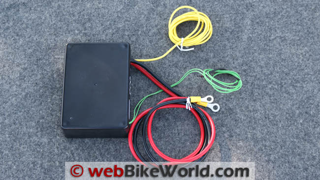
Six optional power leads, each 60 inches or 152.4 cm long, were provided with the evaluation kit that we received directly from Arboreal Systems.
Of the six, two are co-axial plug terminated with weather caps on one end and ready for use with most heated clothing.
The remaining four leads have co-axial connectors on one end and tinned wires on the other end to facilitate home-brew connections.
The co-axial or barrel components are 2.5 mm x 5.5 mm plugs and sockets, pretty much the standard for heated garments and many power port solutions.
I have an observation about the leads. The printed wire is positive; the wire with the grey dashed line is Negative.
Despite the markings being a recognizable standard per se, and even though the leads are optional items and not part of the basic kit, there are no polarity markings or tags on the cables, nor does the manual address any of the optional items.
A quick multimeter check verified the assignments — better safe than sorry.
GPS Connection (Garmin zumo 665): First up, it takes little time to mate the two (very) thin wire leads to one of the supplied power leads on the Garmin GPS using two red Posi-Lock connectors.
With connectivity previously verified, the coaxial connector end of the prepared lead is plugged into the U1 port on the Dispatch 1 power distribution module.
Step by step, I turned on the system, used the Plug button to scroll to the UN1 port, select it with the Red button (indicated by the icon becoming filled in) and, exit via the Plug button. A second later the Garmin screen came to life.
Auxiliary Lighting: Next, I connected the Denali LED Lights (review) set with the 15-degree spot beam lenses. For this test setup I left the light connection harness intact, complete with the relay and the handlebar mounted switch.
Then I simply connected the power wires from the harness to the respective wires of another Dispatch 1 accessory lead.
With this lead connected to the UN2 port on the power distribution module and the port activated via the controller’s menu, one set of Denali LED lights is now on the power management grid.
With the harness switch still connected I can activate the light set via the bar mounted switch or the controller menu.
Heated Clothing: With the cool riding weather we experienced in Florida in December, testing the heated circuits was a real requirement.
One of the specific direct connect leads is plugged into the H1 port on the Dispatch 1 power distribution module and the other end directly into the receptacle on my Gerbings Microwire Heated Jacket Liner (review).
With the graduated output functionality of the four “H” (for Heat) ports on the power distribution module, a controller or rheostat is not needed.
Activating the H1 port energizes the circuit and output to the heated garment can be controlled through 32 linear steps, allowing just the right heating environment to be set.
This is nice and thanks to microwire efficiencies, fast.
By this time in the learning process, two linked features engineered into the Dispatch 1 system become quite evident, with both serving to enhance the user interface.
The first feature is a ~300ms (millisecond) timer that is invoked whenever a button is pushed. The second feature is “reactive”, in that nothing happens until that control is released.
These “delay and positive release activation” features minimize unintentional changes to the attached accessory if a control is accidentally pushed.
The delay provides another benefit as well — a push or “quick stab” of less than 300ms of any button instantly activates the backlighting feature, but only if ambient lighting and backlighting rules are met.
Where to Buy Dispatch Motorcycle Power
See More: Motorcycle Intercom, Motorcycle Accessories, Motorcycle Helmets
Power Management With the Dispatch 1 System
Covering a few management scenarios and more features will help illustrate.
Requirement: Many motorcyclists want the ability to keep ports “always on” or live, even when the system and motorcycle is not running.
This is a valid requirement and one that some manufacturers provide via dedicated outputs or by allowing the user to physically reconfigure the outputs in some manner.
Dispatch 1 Solution: The Dispatch 1 makes this requirement a no-brainer. Any of the ten individual ports can be configured as “always on” by using the “Trigger Config” setup menu.
Simple…and no more setting of physical switches or changing fuse assignments on a device that may not be readily accessible. Been there, done that!
This feature provides the ability to make an output “live” and then shut the motorcycle and system down leaving the needed circuit on. For example, playing the radio while cleaning the bike or farkling.
Or setting up camp in the dark while maintaining the ability to use a low-draw set of auxiliary lights versus the headlights, or a small floodlight on a flexible cord. This makes life better.
Powering or Charging USB Devices: Most USB-powered or other similar low-draw devices can all be used or charged via the system.
A visual cue on the operational screen identifies the “always on” circuits with a small dark plus (+) sign positioned inside the outline of the activated circuit’s icon.
Just remember that circuits configured as “live” will be just that, and it is therefore possible to run the battery down.
Dispatch 1 Fail-Safe: The Dispatch 1 covers the bases here as well.
The latest software release adds an automatic port shutdown if the system voltage drops one (1) Volt below the default alarm threshold voltage (default is 10.50V) or another value as configured by the user.
This means that if the motorcycle is running and there is a voltage drop, the Dispatch 1 will shut down all outputs until the voltage increases.
And more importantly, if the motorcycle is off and the voltage falls below the monitored threshold, the Dispatch 1 will shut down all outputs and itself. This should always result in enough “juice” being left to allow a start in the morning.
Trigger Configuration Exception: There is one exception to the trigger configuration rule. If one of the “always on” circuits is manually switched off while the motorcycle is running, that circuit will be “off” when the motorcycle is shut down, which makes sense. However, when the motorcycle is started and the system powered up which invokes memory settings, this circuit will now be “always on” again.
Device Switching: A recent management feature change that I like is the ability to keep the operational screen of the Dispatch 1 controller module at the ready, rather than having the system revert back to the default screen (showing temperature).
This keeps the operational screen active and circuits directly accessible for rapid switching, such as when using auxiliary lighting systems.
Some may question the use of the Dispatch 1 system as a hot switch in lieu of a discrete on/off switch mounted somewhere on the bike.
But this one feature alone, which I have been using steadily without issue, clearly illustrates the dynamic “management” capability of the system.
Fuses and Circuits: Before leaving this section, one more management aspect needs covering: fuses. While they probably won’t need to be accessed very often once the system is set up as desired, I was changing components on a regular basis for testing and thus changing system loads.
Accordingly, changing the fuses on the individual circuits to reflect use requirements, provide load balancing and maintain safe parameters is and should remain a priority.
Accessing the mini blade type (APM/ATM) fuses for the individual circuits is straight forward if the Dispatch 1 power distribution module is accessible, of course.
Remove the four small Phillips-head sheet screws and wiggle the tight fitting lid off — the individual fuse holders sit on top of the circuit board and are easily changed.
Where to Buy Dispatch Motorcycle Power
See More: Motorcycle Intercom, Motorcycle Accessories, Motorcycle Helmets
Ongoing Dispatch 1 System Use
Life with the Dispatch 1 is good (big period).
Although previous power distribution units that I have used over the years all provided a host of fused connections, none of them are able to provide the discrete voltages available, manage the connections dynamically, or provide visual feedback information like the Dispatch 1 does.
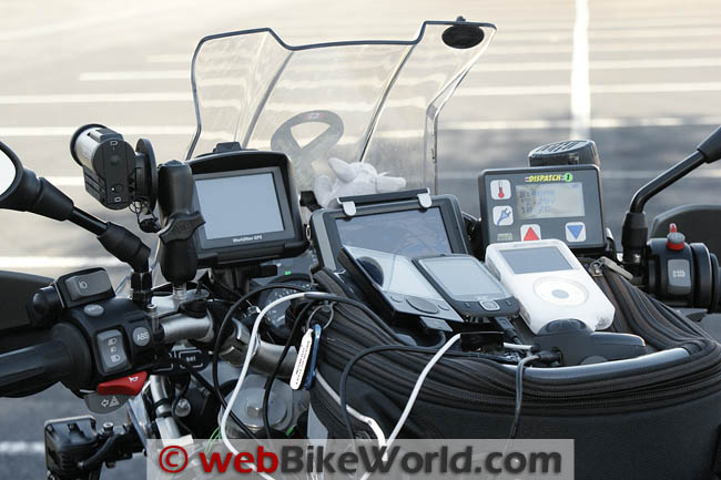
The U1 to U3 connections on the Dispatch 1 power distribution module are the smart USB output ports and I use them constantly via USB extension cables to power a growing list of devices.
One is pretty much dedicated to powering the Sena SMH10 Bluetooth system (review), as that system is designed to allow a direct power connection while being used to save the battery (I only wish more systems could do this!).
Being constantly connected means that the devices are powered directly, with trickle-charging done as needed, and the intercom system is always at maximum efficiency when using the intercom.
For the other two USB ports on the power distribution module, I rotate between the iPod Classic, the zune 120 and HTC Touch mobile phone, along with other devices.
Once I get a co-axial to USB power adapter lead made or sourced for my XM Radio/MP3 receiver, it will get added to the Dispatch 1 grid as well.
With USB charging a de-facto standard, having three USB ports available on demand via the Dispatch 1 controller is really nice: tap on/tap off equals dynamic management.
The registered jack or RJ11 (5V) output port on the power distribution module is meant to be used with a radar detector.
Between the fact that radar detectors are illegal in most provinces and territories and for other reasons, I have never really had the urge to own one. But for those who have one (or two), this power management port makes sense.
Ports H1 through H4 on the Dispatch 1 power distribution module are designated as power outputs for heated garments. Before winter withdrew further north for a few days during our stay in Florida, the H1 and H2 ports were used to provide modulated current to my electrically heated clothing.
The ability to control the output to the clothing over 32 steps using the Red or Blue buttons is very nice. Overall heating control for the heated clothing is vastly improved, compared to the rotary control module I originally used but now no longer needed. With a rider and passenger on board, two or more harnesses from the heated clothing and two of the controllers were put away.
I left the H4 port in service as a switched port and set it to 100 percent output, which provided power to the WorldNav 3500 Cycle GPS (review coming soon).
On my BMW F 800 GS, the H3 provided switched power to the 15A secondary accessory power plug. The switched high output ports, identified as UN1 and UN2 on the Dispatch 1 power distribution module, are intended for use with auxiliary lights and higher consumption accessories.
After successfully using the Garmin zumo 665 GPS on the UN1 port for two days, I put it back on the BMW CANBus accessory plug located under the dummy panel on the F 800 GS, using the already wired BMW Repair Connector harness (identified in Part 3: Installation and Conclusion).
This let me add the second Denali LED light set (with the fog lenses) to UN1 port. While making this change, I removed the harnesses and relays from both light sets and used the accessory leads to wire both sets directly to the distribution module.
In this configuration, the lights are powered by the system and switched on or off directly from the Dispatch 1 Controller. I realize this configuration may not be acceptable to some users, especially if auxiliary lighting is tied in with the on-board lights (by law or desire), but the ability is there.
As an alternative, and if needed, the light switches could be added into the wiring loop. The current bottom line in this regard is that both sets of low-draw LED lights are powered directly by the distribution module and controlled by the user via the control module — about as simple as one could want. And, more wiring has been eliminated.
Initialization and Setup and Conclusion
So far, so good. The Dispatch 1 is exactly what I hoped for and more. There are one or two “rough edges” to speak of, but nothing that keeps it from being the most versatile power distribution system I have ever seen or used.
Part 3 of this review will cover installation of the system on both the F 800 GS and the R 1200 RT, along with system functionality, system observations, the final conclusion and a listing of the system features and specifications for the Dispatch 1 system.
That it is the smartest power management system I have ever seen or used goes without saying. Next is Part Three, which will cover the installation on both the F 800 GS and the R 1200 RT, along with system observations, the conclusion and a list of all of the system features and specifications available.
Next: Part 3 Installation and Conclusion
(Back to Part 1: Overview and Introduction)
Where to Buy Dispatch Motorcycle Power
See More: Motorcycle Intercom, Motorcycle Accessories, Motorcycle Helmets
Owner Comments and Feedback
See details on submitting comments.
Feedback, comments and the product information summary table are located in Part 1: Overview

No Comment