

The Autocom Active-PLUS
Editor’s Note: This is a two-part article on installing an Autocom Active-PLUS motorcycle intercom system.
Part I: Motorcycle Helmet Installation
Part II: Installing the Autocom Active-PLUS on a 2006 Yamaha Road Star Silverado (This page)
After a few days of scooting around fine-tuning the headsets it was time to hook the unit to bike power.
Over a period of several days I encountered few problems with the Autocom kit.
Although I was forced to “adapt/overcome/improvise” when it became obvious that the microphone was suffering from false key-ups due to wind.
Autocom states very clearly that for open-face helmets you need a windsock kit but I overlooked this purchase… oops.
When riding two-up with no accessories connected to the unit (MP3 player, for example) the false key-ups aren’t really that big of a deal.
But once you bring the tunes in it gets a little annoying because the volume drops to 50% and stays lowered for about 5 seconds after whatever noise keying it up stops.
Seems to happen a lot at the good parts of my songs.
Also, forget about singing along!
Lip-synching only, or you’ll key it up and the volume drops revealing how bad of a singer you really are – a bit like saying something stupid in a crowd of people just AFTER everyone stops talking.
I used some “hook” side Velcro cut to the size of the front of the mic disk, a tie-wrap and some foam earpiece pads from a cheap pair of old walkman headsets to make my shade-tree windsock kits but I have a doubt as to the thickness of the actual foam.
I’d be willing to bet the stuff Autocom sells is thicker and denser since it is probably designed to prevent sound ingression whereas the headset foam is designed to let sound it. My solution added about 10mph to the wind threshold (from about 40mph to 50mph) so it’s OK for low-speed cruising.
With the visor down it’s not an issue, but it’s entirely too hot here to be running around like that unless the lorry in front of you is showering you with it’s cargo – also, your voice sounds much louder inside the helmet with it down.
I was not impressed with the bike-to-bike audio quality. I originally used a pair of old Motorola T5710’s but Scott from Autocom had this to say:
“Just to let you know that the T5710 is not the best Motorola out there, I would suggest the T6500 or higher. The T5710 has a very low output volume, very hard to hear at highway speeds.”
I went out and got a pair of T6500R’s but I’m still not impressed.
My wife (in the van) can hear me pretty good but I have a difficult time understanding her; she sounds “tinny” and there is what sounds like interference or something, even when I’m right behind her.
I think it’s more a function of the radios than the Autocom system, however. Autocom sells various Motorola radios and some of them are pretty pricey, but this may be the solution. I’ll need to do some more research on this aspect of it.
Where to Buy Autocom Active-PLUS Motorcycle Intercom
Check Reviews & Prices on Amazon Check Reviews & Prices On RevZillaSee More: Motorcycle Intercom, Motorcycle Accessories, Motorcycle Helmets
Tools Needed
Sidecutters, scissors, 2-inc wide adhesive backed heavy duty Velcro, Zip-ties, Posi-Lock wire connector, DMM (Digital Multi-Meter) and some heat shrink. My son to hand me stuff (“I want to work on the bike too, Daddy!”) and my wife to help with the stuff my son couldn’t.
I had already completed the first step (deciding where to mount the kit) last week. I had the entire thing installed but it was running on battery power, so today’s evolution was hooking it to the bike and generally cleaning up the wires.
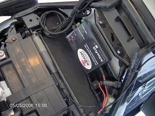
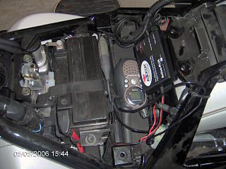
My particular motorcycle allows me to remove the seat quite easily by unlocking the latch with the key in the ignition. I removed the little bag of tools and mounted the box right there using Velcro. If you do this, be sure not to cover the battery compartment with Velcro so you can change the battery easily.
My unit ran for about 5 days on a 9v battery with only a few two-up rides (but lots of MP3) – I had to change it this afternoon, which led to the decision to just wire it in and be done with it.
Bikes are different, so where you put yours will depend on where you have the most room.
Autocom recommends installing it somewhere where it will not get direct water spray on it, and they also advise against sealing it in a bag because the unit needs to breathe. Pick your location carefully so you have access to it if you want to change the rider/passenger volume or hook accessories to it.
The next step is to consider where you will be getting your power from. I chose the rear running lamp since it is powered by the ignition and is always on when the bike is running.
Take care tracing your circuit and pay attention to wire colors – you don’t want to suck power from a critical system like ABS (if you have it) or your brake circuit, in which case your system will only get power when you hit the brakes.
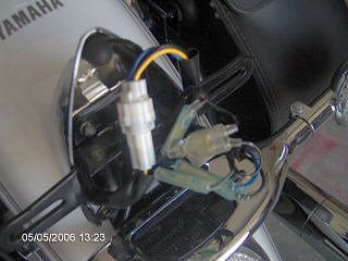
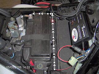
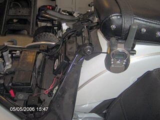
I removed my plate and inspected the wiring – on my bike the running lamp/brake lamp is powered by this big white plug. Black is return (ground), blue is the running lamp and yellow is the brake lamp.
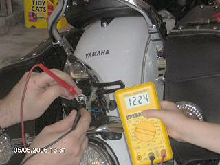
I used my DMM to verify the circuit by disconnecting the plug and measuring the source side with the meter while my wife hit the brakes and the boy held the meter. If you do not have access to a DMM you may want to contact your dealership and ask them if they have an electrical schematic or interconnect drawing of your bike’s electrical system.
You’d also probably get good results by taking your scooter to them and asking the dudes in the service department to show you the wire you need. It’s a good excuse to get out on the bike for a bit.
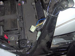
Once the wiring was sorted I back-tracked it into the compartment under the seat and found the blue wire I needed. I disconnected the field side, tested the source side to be sure, then slit the plastic tubing on the field side to expose the wire. I did this because I had more wire to work with on the field side of the plug.
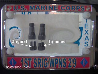
I found that when I put the “vampire tap” Posi-Lock on this little wire the tap spike tended to push the wire aside and not penetrate the sheath.
It also left a small gap between the barrel and the threaded insert because the insert tended to bottom out inside the barrel of the Posi-Lock before it seated fully against the wire.
I overcame this by trimming some of the threaded portion off which allowed for a good seal on the wire once it was installed. When it was time to install the tap I centered the wire in the base with a DMM lead and screwed it together.
Where to Buy Autocom Active-PLUS Motorcycle Intercom
Check Reviews & Prices on Amazon Check Reviews & Prices On RevZillaSee More: Motorcycle Intercom, Motorcycle Accessories, Motorcycle Helmets
Now it’s time to start connecting stuff. Make sure you do this carefully and take all available safety precautions (i.e. ignition off, plug disconnected, etc.). 12 volts isn’t much, but remember it’s not the voltage but the current that bites you.
Accidentally getting bit (even with low current) could startle you causing you to do bad things with tools, like drop them on your pipes/paint/foot/son/cat and any number of other things. When you look in the mirror you are looking at the person most responsible for your own safety, so use caution.
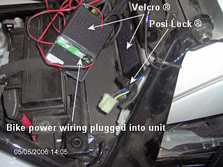
I removed the 9v battery plug/wiring and replaced it with the bike power set. It pulls on and off, but it can be a little tricky because it has little locking tabs on the side so don’t get too rough with it.
You might want to get one side lifted off a bit and then use a small eyeglass screwdriver or something like that to pry it up so you can avoid pulling on the wires. It only goes on one way, but the red/black (power/return) for the 9v option are on the LEFT side of the plug while the same wires are on the RIGHT side of the bike power plug.
This pinout is noted on the printed circuit board right below the plug receptacle in small white letters. I mention this because most people tend to pull something off and put the new one on the same way as the old one.
You’ll need to cut a little tab off of the unit that seals the bottom of the case when you are using a battery, and the reinforced rubber part of the new wiring that passes through the case is not grooved since you need to slide the cover backwards to open the compartment.
Once you get the cover on give it a good tug to make sure the rubber collar on the inside is seated against the inside of the unit housing. You might want to put a tie-wrap on the outside flush with the housing to keep it from pushing back inside in the event you have rowdy pipes and your bike is a mobile earthquake simulator (mine sets off car alarms).
In keeping with the “test before install” school of thought, it’s a good idea to scab in the wiring, power it all up and test it before you start running your wires where you’ll want them. Make sure it works!
I ran the ground lead to the negative side of the battery first. I laid it in with the existing wiring in the cable tray, left some slack, cut it and stripped the bitter end. I slipped some shrink tubing over the wire, crimped the included terminal lug to the wire, slid the heat shrink over it and shrunk it on.
Then I trimmed the positive wire (leaving some slack), slid some heat shrink over the wire and landed it in the Posi-Lock. Because of the difference in size between the Posi-Lock barrel and the wire I put a tie-wrap on to seal it up – it’s a good idea to install the tie-wrap when the heat shrink is still hot so it makes a good watertight seal.
If you have a heat shrink gun that’d be ideal, but if you don’t you can use a match or a cigarette lighter. When using an open flame on heat shrink you need to move the flame back and forth a lot so as not to concentrate too much heat on the tubing or it’ll catch fire, and you don’t want that.
Most hair driers don’t get hot enough, but if you have a soldering iron you can heat it up and put the tip close (but not on) the tubing and the radiated heat will shrink it right up for you.
It’s a good idea to power it up again and test it before you finalize your cabling if your install will require that you bundle slack wiring. I work on an offshore oil rig and powering up a modification intermittently during the install is a good habit to get into – it can save you some real headaches down the road (no pun intended).
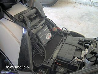
If it works you’re good to go and all you need to do now is finalize the job. I like to leave a job clean and squared away, especially considering someone might want to see how you installed your kit. You don’t want an ugly bird nest under there, right?
Coil your service loops, trim your tie wraps, seal up whatever cable sheath you cut, then have a beverage of your choice and bask in the glory of your work. When you’re finished with your beverage, ride your bike!
Where to Buy Autocom Active-PLUS Motorcycle Intercom
Check Reviews & Prices on Amazon Check Reviews & Prices On RevZillaSee More: Motorcycle Intercom, Motorcycle Accessories, Motorcycle Helmets
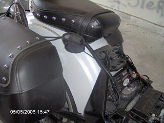
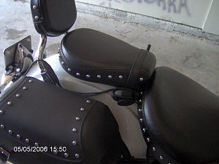
I run a little MP3 player in a cell phone case on the starboard side of the pillion seat, clipped to the strap. I used a hole punch to cut a hole over the power button on the face so I can get to it without removing the unit.
When I want to do bike-to-bike (or in my case, bike-to-van) I run the Motorola on the port side clipped to the same strap. When I’m not using the radio it is stowed under the seat. There is enough slack in both leads to slip them under the seat if I am going to be away from the bike for a while and decide to take my electronics with me or stow them in the saddlebag.
Note that I elected not to use a PTT button on my install for the FRS radio because my grip clusters wouldn’t allow for a good mounting solution within easy reach (to my satisfaction, anyway).
I didn’t want to be fiddling around reaching for a button while riding so I elected to stick with VOX. The Autocom unit handles the VOX, and they suggest if your radio has VOX capability to turn it off as it apparently causes some problems.
Since I only use the radio when the wife isn’t on the bike this doesn’t inhibit the way we do things, although folks who do true bike-to-bike would probably want a PTT for that since they probably wouldn’t want the other riders hearing everything they are saying to their passenger.
Naturally, Autocom sells a PTT loom that would be wired in series with the FRS lead from the unit.
Date Posted: May 2006
See Also: Part I – Installing the Autcom Active-PLUS in the Bell Mag-8 Helmet
Where to Buy Autocom Active-PLUS Motorcycle Intercom
Check Reviews & Prices on Amazon Check Reviews & Prices On RevZillaSee More: Motorcycle Intercom, Motorcycle Accessories, Motorcycle Helmets
Owner Comments and Feedback
See details on submitting comments.

No Comment